Advertisements

EMF equation of a transformer and Voltage Transformation Ratio

In a transformer, source of alternating current is applied to the primary winding. Due to this, the current in the primary winding (called as magnetizing current) produces alternating flux in the core of transformer. This alternating flux gets linked with the secondary winding, and because of the phenomenon of mutual induction an emf gets induced in the secondary winding. Magnitude of this induced emf can be found by using the following EMF equation of the transformer.

EMF equation of the Transformer

Let,
N1 = Number of turns in primary winding
N2 = Number of turns in secondary winding
Φm = Maximum flux in the core (in Wb) = (Bm x A)
f = frequency of the AC supply (in Hz)
emf equation of transformer

As, shown in the fig., the flux rises sinusoidally to its maximum value Φm from 0. It reaches to the maximum value in one quarter of the cycle i.e in T/4 sec (where, T is time period of the sin wave of the supply = 1/f).
Therefore,
average rate of change of flux = Φm /(T/4)    = Φm /(1/4f)
Therefore,
average rate of change of flux = 4f Φm       ....... (Wb/s).
Now,
Induced emf per turn = rate of change of flux per turn

Therefore, average emf per turn = 4f Φm   ..........(Volts).
Now, we know,  Form factor = RMS value / average value
Therefore, RMS value of emf per turn = Form factor X average emf per turn.

As, the flux Φ varies sinusoidally, form factor of a sine wave is 1.11

Therefore, RMS value of emf per turn =  1.11 x 4f Φm = 4.44f Φm.

RMS value of induced emf in whole primary winding (E1) = RMS value of emf per turn X Number of turns in primary winding

          E1 = 4.44f N1 Φm          ............................. eq 1

Similarly, RMS induced emf in secondary winding (E2) can be given as

          E2 = 4.44f N2 Φm.          ............................ eq 2

from the above equations 1 and 2,
emf equation of transformer
This is called the emf equation of transformer, which shows, emf / number of turns is same for both primary and secondary winding.

For an ideal transformer on no load, E1 = V1 and E2 = V2 .
where, V1 = supply voltage of primary winding
            V2 = terminal voltage of secondary winding

Voltage Transformation Ratio (K)

As derived above,
voltage transformation ratio
Where, K = constant
This constant K is known as voltage transformation ratio.
  • If N2 > N1, i.e. K > 1, then the transformer is called step-up transformer.
  • If N2 < N1, i.e. K < 1, then the transformer is called step-down transformer.
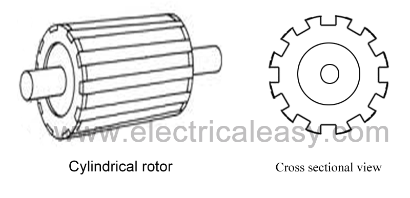
Read More...

Ideal transformer and it's characteristics

An ideal transformer is an imaginary transformer which has
- no copper losses (no winding resistance)
- no iron loss in core
- no leakage flux
In other words, an ideal transformer gives output power exactly equal to the input power. The efficiency of an idea transformer is 100%. Actually, it is impossible to have such a transformer in practice, but ideal transformer model makes problems easier.

Characteristics of ideal transformer

  • Zero winding resistance: It is assumed that, resistance of primary as well as secondary winding of an ideal transformer is zero. That is, both the coils are purely inductive in nature.
  • Infinite permeability of the core: Higher the permeability, lesser the mmf required for flux establishment. That means, if permeability is high, less magnetizing current is required to magnetize the transformer core.
  • No leakage flux: Leakage flux is a part of magnetic flux which does not get linked with secondary winding. In an ideal transformer, it is assumed that entire amount of flux get linked with secondary winding (that is, no leakage flux).
  • 100% efficiency: An ideal transformer does not have any losses like hysteresis loss, eddy current loss etc. So, the output power of an ideal transformer is exactly equal to the input power. Hence, 100% efficiency.

Now, if an alternating voltage V1 is applied to the primary winding of an ideal transformer, counter emf E1 will be induced in the primary winding. As windings are purely inductive, this induced emf E1 will be exactly equal to the apply voltage but in 180 degree phase opposition. Current drawn from the source produces required magnetic flux. Due to primary winding being purely inductive, this current lags 90° behind induced emf E1. This current is called magnetizing current of the transformer Iμ. This magnetizing current Iμ produces alternating magnetic flux Φ. This flux Φ gets linked with the secondary winding and emf E2 gets induced by mutual induction. (Read Faraday's law of electromagnetic induction.) This mutually induced emf E2 is in phase with E2. If closed circuit is provided at secondary winding, E2 causes current I2 to flow in the circuit.
For an ideal transformer, E1I1 = E2I2.

Read More...

Electrical Transformer - Basic construction, working and types

Electrical transformer is a static electrical machine which transforms electrical power from one circuit to another circuit, without changing the frequency. Transformer can increase or decrease the voltage with corresponding decrease or increase in current.

Working principle of transformer

working principle of transformer
 The basic principle behind working of a transformer is the phenomenon of mutual induction between two windings linked by common magnetic flux. The figure at right shows the simplest form of a transformer. Basically a transformer consists of two inductive coils; primary winding and secondary winding. The coils are electrically separated but magnetically linked to each other. When, primary winding is connected to a source of alternating voltage, alternating magnetic flux is produced around the winding. The core provides magnetic path for the flux, to get linked with the secondary winding. Most of the flux gets linked with the secondary winding which is called as 'useful flux' or main 'flux', and the flux which does not get linked with secondary winding is called as 'leakage flux'.  As the flux produced is alternating (the direction of it is continuously changing), EMF gets induced in the secondary winding according to Faraday's law of electromagnetic induction. This emf is called 'mutually induced emf', and the frequency of mutually induced emf is same as that of supplied emf. If the secondary winding is closed circuit, then mutually induced current flows through it, and hence the electrical energy is transferred from one circuit (primary) to another circuit (secondary).

Basic construction of transformer

construction of transformer
Basically a transformer consists of two inductive windings and a laminated steel core. The coils are insulated from each other as well as from the steel core. A transformer may also consist of a container for winding and core assembly (called as tank), suitable bushings to take our the terminals, oil conservator to provide oil in the transformer tank for cooling purposes etc. The figure at left illustrates the basic construction of a transformer.
transformer laminated steel sheet shapes  In all types of transformers, core is constructed by assembling (stacking) laminated sheets of steel, with minimum air-gap between them (to achieve continuous magnetic path). The steel used is having high silicon content and sometimes heat treated, to provide high permeability and low hysteresis loss. Laminated sheets of steel are used to reduce eddy current loss. The sheets are cut in the shape as E,I and L. To avoid high reluctance at joints, laminations are stacked by alternating the sides of joint. That is, if joints of first sheet assembly are at front face, the joints of following assemble are kept at back face.

Types of transformers

Transformers can be classified on different basis, like types of construction, types of cooling etc.

(A) On the basis of construction, transformers can be classified into two types as; (i) Core type transformer and (ii) Shell type transformer, which are described below.
core type and shell type transformer

(i) Core type transformer

In core type transformer, windings are cylindrical former wound, mounted on  the core limbs as shown in the figure above. The cylindrical coils have different layers and each layer is insulated from each other. Materials like paper, cloth or mica can be used for insulation. Low voltage windings are placed nearer to the core, as they are easier to insulate.

(ii) Shell type transformer

The coils are former wound and mounted in layers stacked with insulation between them. A shell type transformer may have simple rectangular form (as shown in above fig), or  it may have a distributed form.

(B) On the basis of their purpose
  1. Step up transformer: Voltage increases (with subsequent decrease in current) at secondary.
  2. Step down transformer: Voltage decreases (with subsequent increase in current) at secondary.
(C) On the basis of type of supply
  1. Single phase transformer
  2. Three phase transformer
(D) On the basis of their use
  1. Power transformer: Used in transmission network, high rating
  2. Distribution transformer: Used in distribution network, comparatively lower rating than that of power transformers.
  3. Instrument transformer: Used in relay and protection purpose in different instruments in industries
    •  Current transformer (CT)
    • Potential transformer (PT)
(E) On the basis of cooling employed
  1. Oil-filled self cooled type
  2. Oil-filled water cooled type
  3. Air blast type (air cooled)

Read More...

Maxwell's right hand grip rule and right handed cork screw rule

magnetic field around a current carrying conductor
We know that a current carrying conductor creates a magnetic field around it. The nature of magnetic field around a straight current carrying conductor is like concentric circles having their center at the axis of the conductor (as shown in the figure at right). The direction of these circular magnetic lines is dependent upon the direction of current. The density of the induced magnetic field is directly proportional to the magnitude of the current.

Direction of the circular magnetic field lines can be given by Maxwell's right hand grip rule or Right handed cork screw rule.

Maxwell's right hand grip rule

maxwell's right hand grip rule
Assume that the current carrying conductor is held in the right hand so that the fingers wrap around the conductor and the thumb is stretched (as shown in the figure at left). If the thumb is along the direction of current, wrapped fingers will show the direction of circular magnetic field lines.

Right handed cork screw rule

right handed cork screw ruleIf a right handed cork screw is assumed to be held along the conductor, and the screw is rotated such that it moves in the direction of the current, direction of magnetic field is same as that of the rotation of the screw.
Read More...

Synchronization of alternator

Synchronization of alternator means connecting an alternator into grid in parallel with many other alternators, that is in a live system of constant voltage and constant frequency. Many alternators and loads are connected into a grid, and all the alternators in grid are having same output voltage and frequency (whatever may be the power). It is also said that the alternator is connected to infinite bus-bar.
A stationary alternator is never connected to live bus-bars, because it will result in short circuit in the stator winding (since there is no generated emf yet). Before connecting an alternator into grid, following conditions must be satisfied:
  1. Equal voltage: The terminal voltage of incoming alternator must be equal to the bus-bar voltage.
  2. Similar frequency: The frequency of generated voltage must be equal to the frequency of the bus-bar voltage.
  3. Phase sequence: The phase sequence of the three phases of alternator must be similar to that of the grid or bus-bars.
  4. Phase angle: The phase angle between the generated voltage and the voltage of grid must be zero.
The first condition of voltage equality can be satisfied by a voltmeter. To satisfy the conditions of equal frequency and identical phases, one of the following two methods can be used:
(i) Synchronization using incandescent lamp
(ii) Synchronization using synchroscope.

Synchronization of alternator using incandescent lamp

 synchronization of alternator using incandescent lamps

Let, alternator 2 is to be synchronized in a grid and the alternator 1 is already in the grid as shown in above figure. The alternator 2 is connected to grid through three synchronizing lamps (L1, L2 and L3) as shown in above figure.  If the speed of the alternator 2 is not such that the frequency of output voltage is equal to the frequency of the grid, there will also be a phase difference in the voltages, and in this case the lamps will flicker. Three lamps are connected asymmetrically, because if they were connected symmetrically, they would glow or dark out simultaneously (if the phase rotation is same as that of bus-bars). Asymmetrically connected lamps indicate whether the incoming machine is running slower or faster. If the alternator 2 is running slower, the phase rotation of alternator 2 will appear to be clockwise relative to the phase rotation of the grid and the lamps will light up in the order 3,2,1;3,2,1 .... If the alternator 2 is running faster, the phase rotation of alternator 2 will appear to be anticlockwise relative to the phase rotation of the grid and the lamps will light up in the order 1,2,3;1,2,3....
When the speed of the alternator 2 reaches so that, the frequency and phase rotation of output voltage is similar to that of the grid voltage, lamp L1 will go dark and lamps L2 and L3 will dimly but equally glow (as they are connected between different phases and due to this there will be phase difference of 120 degree). The synchronization is done at this very moment. This method of synchronization is sometimes also known as 'two bright and one dark method'.

Drawbacks of 'synchronization using incandescent lamps' method are:
  • Synchronization by using incandescent lamps depends on the correct judgement of the operator.
  • This method does not tell how slow or fast the machine is.
  • To use this method for high voltage alternators, extra step down transformers need to be added as ratings of lamps are normally low.

Synchronization of alternator using synchroscope

synchronization of alternator using synchroscope
A synchroscope is a device which shows the correct instant of closing the synchronizing switch. Synchroscope has a pointer which rotates on the dial. The pointer rotates anticlockwise if the machine is running slower or it rotates clockwise if the machine is running fast. The correct instant of closing syncronizing switch is when the pointer is straight upwards.

Read More...

Salient pole rotor vs. non-salient pole rotor

Rotors of an electrical machine are classified as: (i) Salient pole rotors and (ii) Non-salient pole rotors. Both types are explained below.

Salient pole rotor

salient pole rotor

In salient pole type of rotor consist of large number of projected poles (salient poles) mounted on a magnetic wheel. Construction of a salient pole rotor is as shown in the figure at left. The projected poles are made up from laminations of steel. The rotor winding is provided on these poles and it is supported by pole shoes.
  • Salient pole rotors have large diameter and shorter axial length.
  • They are generally used in lower speed electrical machines, say 100 RPM to 1500 RPM.
  • As the rotor speed is lower, more number of poles are required to attain the required frequency. (Ns = 120f / P   therefore, f = Ns*p/120   i.e. frequency is proportional to number of poles). Typically number of salient poles is between 4 to 60.
  • Flux distribution is relatively poor than non-salient pole rotor, hence the generated emf waveform is not as good as cylindrical rotor.
  • Salient pole rotors generally need damper windings to prevent rotor oscillations during operation.
  • Salient pole synchronous generators are mostly used in hydro power plants.

Non-salient pole (cylindrical) rotor

non-salient pole (cylindrical) rotor

Non-salient pole rotors are cylindrical in shape having parallel slots on it to place rotor windings. It is made up of solid steel. The construction of non-salient pole rotor (cylindrical rotor) is as shown in figure above. Sometimes, they are also called as drum rotor.
  • They are smaller in diameter but having longer axial length.
  • Cylindrical rotors are used in high speed electrical machines, usually 1500 RPM to 3000 RPM.
  • Windage loss as well as noise is less as compared to salient pole rotors.
  • Their construction is robust as compared to salient pole rotors.
  • Number of poles is usually 2 or 4.
  • Damper windings are not needed in non-salient pole rotors.
  • Flux distribution is sinusoidal and hence gives better emf waveform.
  • Non-salient pole rotors are used in  nuclear, gas and thermal power plants.

Read More...

Fleming's left hand rule and right hand rule

If a current carrying conductor placed in a magnetic field, it experiences a force due to the magnetic field. On the other hand, if a conductor moved in a magnetic field, an emf gets induced across the conductor (Faraday's law of electromagnetic induction).
John Ambrose Fleming introduced two rules to determine the direction of motion (in motors) or the direction of induced current (in generators). The rules are called as Fleming's left hand rule (for motors) and Fleming's right hand rule (for generators).

Fleming's left hand rule

Fleming's left hand rule
Whenever a current carrying conductor is placed in a magnetic field, the conductor experiences a force which is perpendicular to both the magnetic field and the direction of current. According to Fleming's left hand rule, if the thumb, fore-finger and middle finger of the left hand are stretched to be perpendicular to each other as shown in the illustration at left, and if the fore finger represents the direction of magnetic field, the middle finger represents the direction of current, then the thumb represents the direction of force. Fleming's left hand rule is applicable for motors.

How to remember Fleming's left hand rule?

Method 1: Relate the thumb with thrust, fore finger with field and center-finger with current as explained below.
  • The Thumb represents the direction of Thrust on the conductor (force on the conductor).
  • The Fore finger represents the direction of the magnetic Field.
  • The Center finger (middle finger) the direction of the Current.
Method 2: Relate the Fleming's left-hand rule with FBI (wait! NOT with the Federal Bureau of Investigation). Here, F for Force, B is the symbol of magnetic flux density and I is the symbol of Current. Attribute these letters F,B,I to the thumb, first finger and middle finger respectively.

Fleming's right hand rule

[NOT to be confused with Maxwell's right-hand grip rule]

Fleming's right hand rule
Fleming's right hand rule is applicable for electrical generators. As per Faraday's law of electromagnetic induction, whenever a conductor is forcefully moved in an electromagnetic field, an emf gets induced across the conductor. If the conductor is provided a closed path, then the induced emf causes a current to flow. According to the Fleming's right hand rule, the thumb, fore finger and middle finger of the right hand are stretched to be perpendicular to each other as shown in the illustration at right, and if the thumb represents the direction of the movement of conductor, fore-finger represents direction of the magnetic field, then the middle finger represents direction of the induced current.

How to remember Fleming's right hand rule?

You can follow the same methods mentioned above for Fleming's left hand rule. In this case, you just have to consider your right hand instead of the left hand.
Read More...