Advertisements

Understanding Basics of Power Electronics

Controlling the flow of electrical energy by switching electronic circuits is what power electronics is all about. It is the technology that is behind the concept of power converters, power inverters, motor drives, switching power supplies etc. The first high power electronic device was Mercury-Arc valves. This was a type of electrical rectifier that was used for converting high Alternating current into Direct Current.

Today power electronic uses components like diodes, GTO’s and transistors etc. In power electronics a substantial amount of electronic energy is processed. The most common type is an AC/DC converter that is used in most of our daily electronic devices like Computers, Battery Chargers, and Television Set etc.

Power electronics is one of the core subjects for an electrical engineer. This is a brief description about the various sub topics that come under power electronics.

Understanding AC and DC current

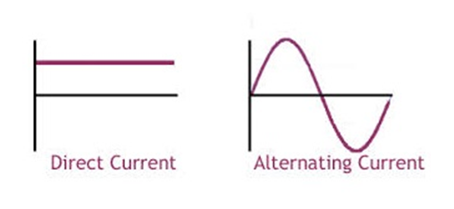
Electricity flows in two ways – Alternating Current or Direct Current . The difference between the two is the way the electron flows.
DC and AC current

Owing to Thomas Edison - DC power was born by creating a magnetic field near a wire, which caused the electrons to flow in a single direction, from negative to positive.

Nikola Tesla came up with AC power because a it was a safer way to transmit power over large city distances. Instead of using a steady magnet, he used a rotating magnet. So as the magnets position changed so did the flow of electrons.

Difference between AC and DC

Alternating CurrentDirect Current
The electrons keep on switching their path. AC current can travel over longer distances.The electrons flow in one direction. DC current cannot travel far otherwise it would lose energy.
Rotating magnetismSteady magnetism
Frequency of an AC current is usually 50Hz or 60Hz. i.e. current is varying over time.Frequency of DC current is zero. i.e. Current is constant over a period of time.
Used popularly for many applications like fans, air conditioners. Regular supply to homes is AC.Used mostly where mobility of electric power is essential. e.g. cell phones, batteries in vehicles etc.

Rectifier

This is an electronic device that converts alternating current to direct current. This entire process is called as rectification. Rectifiers can take many forms like mercury arc valves, semi-conductor diodes, various silicon based semi-conductor switches etc.

What are Diodes, GTO and Transistors?

Diodes:

It is a semiconductor device with two terminals that allows flow of current in one direction. It has low resistance to current in one direction and a very high resistance on the other. It is a vacuum tube that has two electrodes – a plate (anode) and a heated cathode.
vacuum tube diode

A semiconductor diode was the first semiconductor electronic devices. Most diodes are made of silicon, while selenium or germanium is also used sometimes. Because a diode allows electric current to pass one way but not the other, it is used as a rectifier to convert AC to DC current.

Diodes are also used as signal limiters, voltage regulators, switches, signal modulators, signal mixers etc.
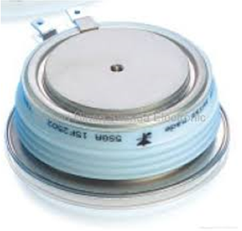
GTO thyristor

GTO:

Gate Turn-Off Thyristor, is a high powered semi-conductor device. It differs from a normal Thyristor. Unlike them a GTO has a fully controllable switch that can be tuned off and on by a third lead i.e. the Gate lead.

A normal thyristor does not have a fully controllable switch i.e., which can be turned on and off at will. Once it has been turned on or fired, it remains turned on till a turn off state occurs. Which could be anything like a reverse voltage or if the current flowing falls below a certain threshold value.

A GTO can be turned on by a gate signal and can be turned off by one which has negative polarity.

transistor

Transistors:

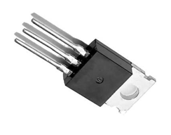
This is semi-conductor device that is used for amplifying and switching electronic signals and power. A transistor has 3 terminals. When voltage or current is applied to one pair of terminal it changes through the other pair. The output power could be higher than the input, a transistor can amplify signals. Most of the transistors are found in integrated circuits.

The three leads that the transistor has are – Base, collector and Emitter. One of the most used transistors is MOSFET.

MOSFET

MOSFET:

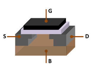
It stand for Metal Oxide Semiconductor Field Effect Transistor. This is a type of transistors that is used for amplifying or switching electronic signals. Though a MOSFET is a 4 terminal device – Source, Gate, Drain and Body. But as the Body Terminal and the Source Terminal are often connected to each other internally, therefore only three terminals appear in electrical diagrams. MOSFET is one of the most common transistors in both digital and analog circuits.


author
Author Bio: Trisha is a professional writer and adviser on education and career. She is an ardent reader, a traveler and a passionate photographer. She wants to explore the world and write about whatever comes across her way.

Read More...

Permanent magnet DC (PMDC) motors

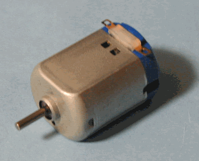
Basic configuration of a permanent magnet DC motor is very similar to that of a normal DC motor. The working principle of any DC motor is same, i.e. when a current carrying conductor is placed in a magnetic field, it experiences a force. A permanent magnet DC motor also works on the same principle.
permanent magnet dc motor

Construction

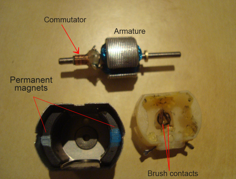
In a PMDC motor, permanent magnets (located in stator) provide magnetic field, instead of stator winding. The stator is usually made from steel in cylindrical form. Permanent magnets are usually made from rare earth materials or neodymium.

The rotor is slotted armature which carries armature winding. Rotor is made from layers of laminated silicon steel to reduce eddy current losses. Ends of armature winding are connected to commutator segments on which the brushes rest. Commutator is made from copper and brushes are usually made from carbon or graphite. DC supply is applied across these brushes. The commutator is in segmented form to achieve unidirectional torque. The reversal of direction can be easily achieved by reversing polarity of the applied voltage.

The image below shows the construction of Permanent Magnet DC Motor 

construction of permanent magnet dc motor
Permanent Magnet DC motor (disassembled)

Characteristics

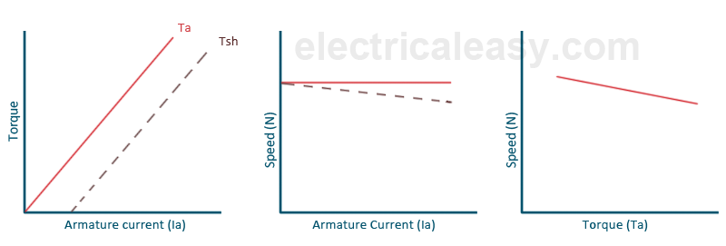
Characteristics of PMDC motors are similar to the characteristics of dc shunt motor in terms of torque, speed and armature current. However, speed-torque characteristics are more linear and predictable in PMDC motors.
characteristics of permanent magnet dc motors

Applications of Permanent Magnet DC Motors

Permanent magnet dc motors are extensively used where smaller power ratings are required, e.g. in toys, small robots, computer disc drives etc. 

Advantages

  1. For smaller ratings, use of permanent magnets reduces manufacturing cost.
  2. No need of field excitation winding, hence construction is simpler.
  3. No need of electrical supply for field excitation, hence PMDC motor is relatively more efficient.
  4. Relatively smaller in size
  5. Cheap in cost

Disadvantages

  1. Since the stator in PMDC motor consists of permanent magnets, it is not possible to add extra ampere-turns to reduce armature reaction. Thus armature reaction is more in PMDC motors.
  2. Stator side field control, for controlling speed of the motor, is not possible in pemanent magnet dc motors.

Read More...

Synchronous generator vs. Induction generator

AC machines can be further classified as Induction machines and Synchronous machines. And hence, AC generators as Synchronous generators (commonly referred as alternators) and Induction generators (or asynchronous generators).

There is significant difference between operating principles of synchronous and induction machines. For now, let us discuss the difference between synchronous generator and induction generator.

Difference between synchronous generator and induction generator


  • In a synchronous generator, the waveform of generated voltage is synchronized with (directly corresponds to) the rotor speed. The frequency of output can be given as f = N * P / 120 Hz. where N is speed of the rotor in rpm and P is number of poles.

    In case of inductions generators, the output voltage frequency is regulated by the power system to which the induction generator is connected. If induction generator is supplying a standalone load, the output frequency will be slightly lower (by 2 or 3%) that calculated from the formula f = N * P / 120.
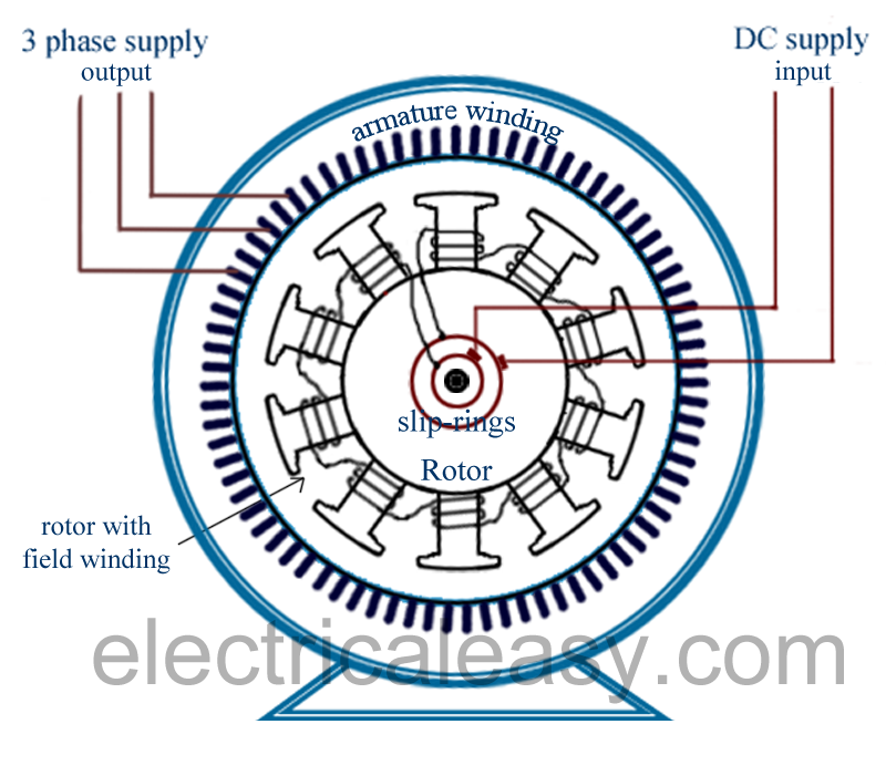
  • Separate DC excitation system is required in an alternator (synchronous generator).

    Induction generator takes reactive power from the power system for field excitation. If an induction generator is meant to supply a standalone load, a capacitor bank needs to be connected to supply reactive power.
  • Construction of induction generator is less complicated as it does not require brushes and slip ring arrangement. Brushes are required in synchronous generator to supply DC voltage to the rotor for excitation.

Basic differences between induction generators and synchronous generators can be better understood from the figures shown below 

Induction generator

induction generator

Synchronous generator

synchronous generator


Read More...

Parallel operation of shunt generators

Normally the generators are coupled in parallel at most of the power station through bus-bars. Bus-bars have positive and negative terminals and they must be dense thick copper bars. The positive and negative terminals of the bus-bars are connected to the positive and negative terminal of the generator respectively.

parallel operation of shunt generators


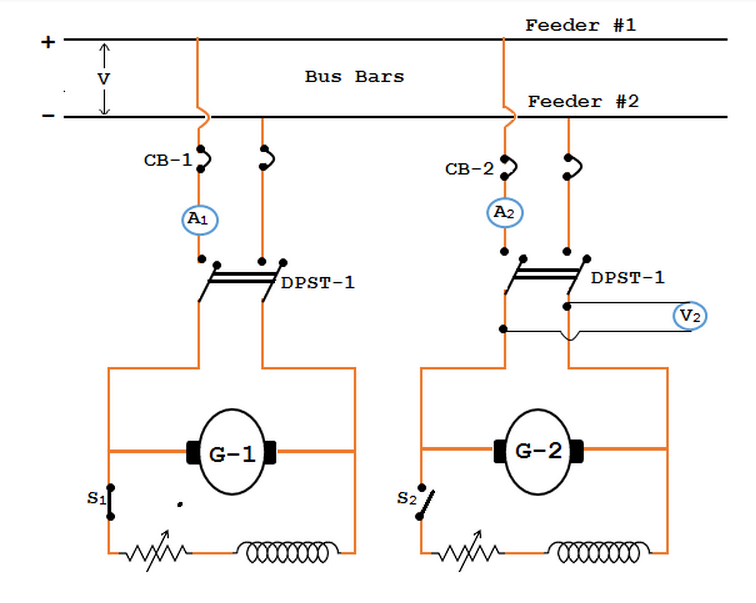
The above figure shows the shunt generator No.1 is connected to the bus-bars and delivering load. The shunt Generator No.2 is connected in parallel to the Generator No.1. When the load on the generator No.1 increases beyond its rated capacity, immediately the second shunt generator operate and wish the first generator to come across the raised load demand.
The paralleling of generator No.2 with the generator No.1 procedures are as follows:
  • First the prime mover of second generator is taken up to the rated speed. Once starts running at its rated speed the field circuit of the second switch S2 is closed.
  • Afterward close the second breaker (ie. CB-2) and the excitation of second generator is varied till it’s generates voltage identical to the bus-bars voltage. It is shown by voltmeter V2.
  • Now the second generator is in parallel with the generator No.1. The generator no.2 will not supply any load when it is connected in parallel with generator No.1, since its generated EMF is same as that of bus-bars voltage. At this juncture the generator is assumed to be “floating” on the bus-bars.
  • Once generator no.2 supply any current, then its generated voltage E ought to be more than the bus-bars voltage V. In such case, the current delivered by it is I = (E - V)/Ra. The generator No.2 can be made to supply appropriate load by raising the field current and so the induced EMF.
  • By varying the field excitation, the load might be lifted from one shunt generator to another. In consequence if generator No.1 needs to be halt, then the entire load moved onto the generator No.2 if it has the ability to deliver that load. In such case, decrease the current delivered by generator NO.1 to zero. It is shown in ammeter A1. Finally open the circuit breaker No.1 and then S1 switch.

Author: CSV is an electrical engineer living and working in India. He regularly writes and enjoys sharing Technical Information in the diversified field of engineering.
Read More...

Induction Generator working theory

Just like a DC Machine, a same induction machine can be used as an induction motor as well as an induction generator, without any internal modifications. Induction generators are also called as asynchronous generators.
Before starting to explain how an induction (asynchronous) generator works, I assume that you know the working principle of an induction motor. In an induction motor, the rotor rotates because of slip (i.e. relative velocity between the rotating magnetic field and the rotor). Rotor tries to catch up the synchronously rotating field of the stator but never succeeds. If rotor catches up the synchronous speed, the relative velocity will be zero, and hence rotor will experience no torque.
But what if the rotor is rotating at a speed more than synchronous speed?


How induction generators work?

  • Consider, an AC supply is connected to the stator terminals of an induction machine. Rotating magnetic field produced in the stator pulls the rotor to run behind it (the machine is acting as a motor).
  • Now, if the rotor is accelerated to the synchronous speed by means of a prime mover, the slip will be zero and hence the net torque will be zero. The rotor current will become zero when the rotor is running at synchronous speed.
  • If the rotor is made to rotate at a speed more than the synchronous speed, the slip becomes negative. A rotor current is generated in the opposite direction, due to the rotor conductors cutting stator magnetic field. 
  • This generated rotor current produces a rotating magnetic field in the rotor which pushes (forces in opposite way) onto the stator field. This causes a stator voltage which pushes current flowing out of the stator winding against the applied voltage. Thus, the machine is now working as an induction generator (asynchronous generator).
how induction generators work

Induction generator is not a self-excited machine. Therefore, when running as a generator, the machine takes reactive power from the AC power line and supplies active power back into the line. Reactive power is needed for producing rotating magnetic field. The active power supplied back in the line is proportional to slip above the synchronous speed.

Self-excited induction generator

It is clear that, an induction machine needs reactive power for excitation, regardless whether it is operating as a generator or a motor. When an induction generator is connected to a grid, it takes reactive power from the grid. But what if we want to use an induction generator to supply a load without using an external source (e.g. grid)?
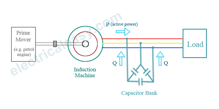
A capacitor bank can be connected across the stator terminals to supply reactive power to the machine as well as to the load. When the rotor is rotated at an enough speed, a small voltage is generated across the stator terminals due to residual magnetism. Due to this small generated voltage, capacitor current is produced which provides further reactive power for magnetization.
self excited induction generator


Applications of induction generators: Induction generators produce useful power even at varying rotor speeds. Hence, they are suitable in wind turbines.

Advantages: Induction or asynchronous generators  are more rugged and require no commutator and brush arrangement (as it is needed in case of synchronous generators).

One of the major disadvantage of induction generators is that they take quite large amount of reactive power.


Read More...