Advertisements

Three Phase Transformer

Usually power is generated and distributed in three phase system, and therefore it is obvious that we would need three phase transformers to step up and step down voltages. Although, it is practically possible to use three suitably interconnected 'single phase transformers' instead of one 'three phase transformer', the following advantages of three phase transformers  encourage their use -
  • One 'three phase transformer' occupies less space than a gang of three 'single phase transformers'.
  • Single 'three phase' unit is more economical
  • The overall bus-bar structure, switchgear and installation of  'three phase transformer' is simpler.

Construction of three phase transformer

Three phase transformers can be of core type or shell type (just like single phase transformers). The constructional details of core type as well as shell type three phase transformers are as follows.

Core type construction

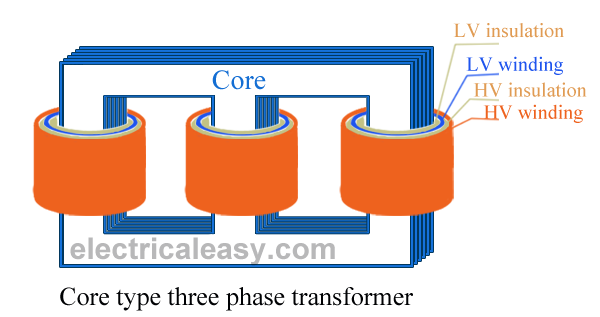
Construction of core type three phase transformer
 The construction of a core type three phase transformer is as shown in the figure. The core consists of three legs or limbs. As usual, the core is made up of thin laminated sheets to reduce eddy current losses. Each limb has primary and secondary windings in cylindrical shape (former wound) arranged concentrically. The construction is well illustrated in the figure.

Shell type construction

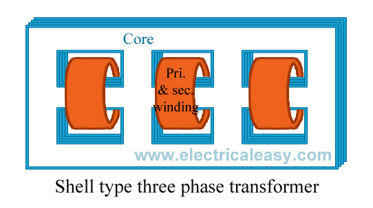
Construction of shell type three phase transformer
 In a shell type three phase transformer, three phases are more independent than they are in core type. Each phase has its individual magnetic circuit. The construction of shell type three phase transformer is illustrated in the figure at right. The construction is similar to that of three single phase shell type transformers kept on the top of each other.


 The basic working principle of a three phase transformer is similar to the working principle of a single phase transformer. Power from primary is transferred to the secondary by the phenomenon of mutual induction.
The main drawback in a three phase transformer is that, even if fault occurs in one phase, the whole transformer is removed from service for repairs.


Read More...

Auto Transformer

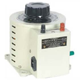
auto transformer
  An auto transformer is an electrical transformer having only one winding. The winding has at least three terminals which is explained in the construction details below.

Some of the advantages of auto-transformer are that,
  • they are smaller in size, 
  • cheap in cost, 
  • low leakage reactance,
  • increased kVA rating, 
  • low exciting current etc. 
An example of application of auto transformer is, using an US electrical equipment rated for 115 V supply (they use 115 V as standard) with higher Indian voltages. Another example could be in starting method of three phase induction motors.

Construction of auto transformer

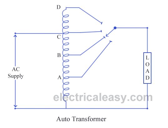
construction of auto transformer
 An auto transformer consists of a single copper wire, which is common in both primary as well as secondary circuit. The copper wire is wound a laminated silicon steel core, with at least three tappings taken out. Secondary and primary circuit share the same neutral point of the winding. The construction is well explained in the diagram. Variable turns ratio at secondary can be obtained by the tappings of the winding (as shown in the figure), or by providing a smooth sliding brush over the winding. Primary terminals are fixed.
Thus, in an auto transformer, you may say, primary and secondary windings are connected magnetically as well as electrically.

Working of auto transformer

As I have described just above, an auto transformer has only one winding which is shared by both primary and secondary circuit, where number of turns shared by secondary are variable. EMF induced in the winding is proportional to the number of turns. Therefore, the secondary voltage can be varied by just varying secondary number of turns.
As winding is common in both circuits, most of the energy is transferred by means of electrical conduction and a small part is transferred through induction.

The considerable disadvantages of an auto transformer are,
  • any undesirable condition at primary will affect the equipment at secondary (as windings are not electrically isolated),
  • due to low impedance of auto transformer, secondary short circuit currents are very high,
  • harmonics generated in the connected equipment will be passed to the supply.

Read More...

Sumpner's test or Back-to-Back test on Transformer

Sumpner's test or back to back test on transformer is another method for determining transformer efficiency, voltage regulation and heating under loaded conditions. Short circuit and open circuit tests on transformer can give us parameters of equivalent circuit of transformer, but they can not help us in finding the heating information. Unlike O.C. and S.C. tests, actual loading is simulated in Sumpner's test. Thus the Sumpner's test give more accurate results of regulation and efficiency than O.C. and S.C. tests.

Sumpner's test

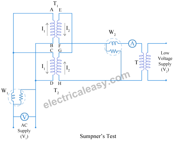
Sumpner's test or back to back test can be employed only when two identical transformers are available. Both transformers are connected to supply such that one transformer is loaded on another. Primaries of the two identical transformers are connected in parallel across a supply. Secondaries are connected in series such that emf's of them are opposite to each other. Another low voltage supply is connected in series with secondaries to get the readings, as shown in the circuit diagram shown below.
sumpner's test of back to back test on transformer

In above diagram, T1 and T2 are identical transformers. Secondaries of them are connected in voltage opposition, i.e. EEF and EGH. Both the emf's cancel each other, as transformers are identical. In this case, as per superposition theorem, no current flows through secondary. And thus the no load test is simulated. The current drawn from V1 is 2I0, where I0 is equal to no load current of each transformer. Thus input power measured by wattmeter W1 is equal to iron losses of both transformers.
i.e. iron loss per transformer Pi = W1/2.

Now, a small voltage V2 is injected into secondary with the help of a low voltage transformer. The voltage V2 is adjusted so that, the rated current I2 flows through the secondary. In this case, both primaries and secondaries carry rated current. Thus short circuit test is simulated and wattmeter W2 shows total full load copper losses of both transformers.
i.e. copper loss per transformer PCu = W2/2.

From above test results, the full load efficiency of each transformer can be given as -


Read More...

Open circuit and Short circuit Test on transformer

These two transformer tests are performed to find the parameters of equivalent circuit of transformer and losses of the transformer. Open circuit test and short circuit test on transformer are very economical and convenient because they are performed without actually loading of the transformer.

Open circuit or No load test on Transformer

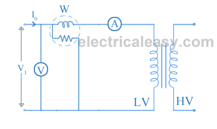
Open circuit test or no load test on a transformer is performed to determine 'no load loss (core loss)' and 'no load current I0'. The circuit diagram for open circuit test is shown in the figure below.


open circuit or no load test on transformer

Usually high voltage (HV) winding is kept open and the low voltage (LV) winding is connected to its normal supply. A wattmeter (W), ammeter (A) and voltmeter (V) are connected to the LV winding as shown in the figure. Now, applied voltage is slowly increased from zero to normal rated value of the LV side with the help of a variac. When the applied voltage reaches to the rated value of the LV winding, readings from all the three instruments are taken.

The ammeter reading gives the no load current I0. As I0 itself is very small, the voltage drops due to this current can be neglected.

The input power is indicated by the wattmeter (W). And as the other side of transformer is open circuited, there is no output power. Hence, this input power only consists of core losses and copper losses. As described above, no-load current is so small that these copper losses can be neglected. Hence, now the input power is almost equal to the core losses. Thus, the wattmeter reading gives the core losses of the transformer.

Sometimes, a high resistance voltmeter is connected across the HV winding. Though, a voltmeter is connected, HV winding can be treated as open circuit as the current through the voltmeter is negligibly small. This helps in to find voltage transformation ratio (K).

The two components of no load current can be given as,


Iμ = I0sinΦ0   and    Iw = I0cosΦ0.
cosΦ0 (no load power factor) = W / (V1I0). ... (W = wattmeter reading)

From this, shunt parameters of equivalent circuit of transformer (X0 and R0) can be calculated as


X0 = V1/Iμ  and  R0 = V1/Iw.

(These values are referring to LV side of the transformer.)
Hence, it is seen that open circuit test gives core losses of transformer and shunt parameters of the equivalent circuit.

Short circuit or Impedance test on Transformer

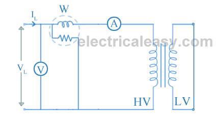
The connection diagram for short circuit test or impedance test on transformer is as shown in the figure below. The LV side of transformer is short circuited and wattmeter (W), voltmere (V) and ammeter (A) are connected on the HV side of the transformer. Voltage is applied to the HV side and increased from the zero until the ammeter reading equals the rated current. All the readings are taken at this rated current.

short circuit or impedance test on transformer
The ammeter reading gives primary equivalent of full load current (Isc).

The voltage applied for full load current is very small as compared to rated voltage. Hence, core loss due to small applied voltage can be neglected. Thus, the wattmeter reading can be taken as copper loss in the transformer.

Therefore, W = Isc2Req....... (where Req is the equivalent resistance of transformer)
 Zeq = Vsc/Isc.

Therefore, equivalent reactance of transformer can be calculated from the formula  Zeq2 = Req2 + Xeq2.

These, values are referred to the HV side of the transformer.
Hence, it is seen that the short circuit test gives copper losses of transformer and approximate equivalent resistance and reactance of the transformer.

Why Transformers are rated in kVA?

From the above transformer tests, it can be seen that Cu loss of a transformer depends on current, and iron loss depends on voltage. Thus, total transformer loss depends on volt-ampere (VA). It does not depend on the phase angle between voltage and current, i.e. transformer loss is independent of load power factor. This is the reason that transformers are rated in kVA.

Read More...

Equivalent circuit of Transformer

In a practical transformer -
(a) Some leakage flux is present at both primary and secondary sides. This leakage gives rise to leakage reactances at both sides, which are denoted as X1 and X2 respectively.
(b) Both the primary and secondary winding possesses resistance, denoted as R1 and R2 respectively. These resistances causes voltage drop as, I1R1 and I2R2 and also copper loss I12R1 and I22R2.
(c) Permeability of the core can not be infinite, hence some magnetizing current is needed. Mutual flux also causes core loss in iron parts of the transformer.
We need to consider all the above things to derive equivalent circuit of a transformer.

Equivalent circuit of transformer

Resistances and reactances of transformer, which are described above, can be imagined separately from the windings (as shown in the figure below). Hence, the function of windings, thereafter, will only be the transforming the voltage.
The no load current I0 is divided into, pure inductance X0 (taking magnetizing components Iμ) and non induction resistance R0 (taking working component Iw) which are connected into parallel across the primary. The value of E1 can be obtained by subtracting I1Z1 from V1. The value of R0 and X0 can be calculated as, R0 = E1 / Iw and X0 = E1 / Iμ.

But, using this equivalent circuit does not simplifies the calculations. To make calculations simpler, it is preferable to transfer current, voltage and impedance either to primary side or to the secondary side. In that case, we would have to work with only one winding which is more convenient.

From the voltage transformation ratio, it is clear that,
E1 / E2 = N1 / N2 = K

Now, lets refer the parameters of secondary side to primary.
Z2 can be referred to primary as Z2'
where, Z2' = (N1/N2)2Z2 = K2Z2.   ............where K= N1/N2.
that is, R2'+jX2' = K2(R2+jX2)
equating real and imaginary parts,
R2' =  K2R2 and X2' = K2X2 .
And V2' = KV2
The following figure shows the equivalent circuit of transformer with secondary parameters referred to the primary.

Now, as the values of winding resistance and leakage reactance are so small that, V1 and E1 can be assumed to be equal. Therefore, the exciting current drawn by the parallel combination of  R0 and X0 would not affect significantly, if we move it to the input terminals as shown in the figure below.

Now, let R1 + R2' = R'eq  and X1 + X2' = X'eq
Then the equivalent circuit of transformer becomes as shown in the figure below

Approximate equivalent circuit of transformer

If only voltage regulation is to be calculated, then even the whole excitation branch (parallel combination of R0 and X0) can be neglected. Then the equivalent circuit becomes as shown in the figure below

Read More...

Transformer - Losses and Efficiency

Losses in transformer

In any electrical machine, 'loss' can be defined as the difference between input power and output power. An electrical transformer is an static device, hence mechanical losses (like windage or friction losses) are absent in it. A transformer only consists of electrical losses (iron losses and copper losses). Transformer losses are similar to losses in a DC machine, except that transformers do not have mechanical losses.
Losses in transformer are explained below -

(i) Core losses or Iron losses

Eddy current loss and hysteresis loss depend upon the magnetic properties of the material used for the construction of core. Hence these losses are also known as core losses or iron losses.
  • Hysteresis loss in transformer: Hysteresis loss is due to reversal of magnetization in the transformer core. This loss depends upon the volume and grade of the iron, frequency of magnetic reversals and value of flux density. It can be given by, Steinmetz formula:
    Wh= ηBmax1.6fV (watts)
    where,   η = Steinmetz hysteresis constant
                 V = volume of the core in m3
  • Eddy current loss in transformer: In transformer, AC current is supplied to the primary winding which sets up alternating magnetizing flux. When this flux links with secondary winding, it produces induced emf in it. But some part of this flux also gets linked with other conducting parts like steel core or iron body or the transformer, which will result in induced emf in those parts, causing small circulating current in them. This current is called as eddy current. Due to these eddy currents, some energy will be dissipated in the form of heat.

 (ii) Copper loss in transformer

Copper loss is due to ohmic resistance of the transformer windings.  Copper loss for the primary winding is I12R1 and for secondary winding is I22R2. Where, I1 and I2 are current in primary and secondary winding respectively, R1 and R2 are the resistances of primary and secondary winding respectively. It is clear that Cu loss is proportional to square of the current, and current depends on the load. Hence copper loss in transformer varies with the load.

Efficiency of Transformer

Just like any other electrical machine, efficiency of a transformer can be defined as the output power divided by the input power. That is  efficiency = output / input .
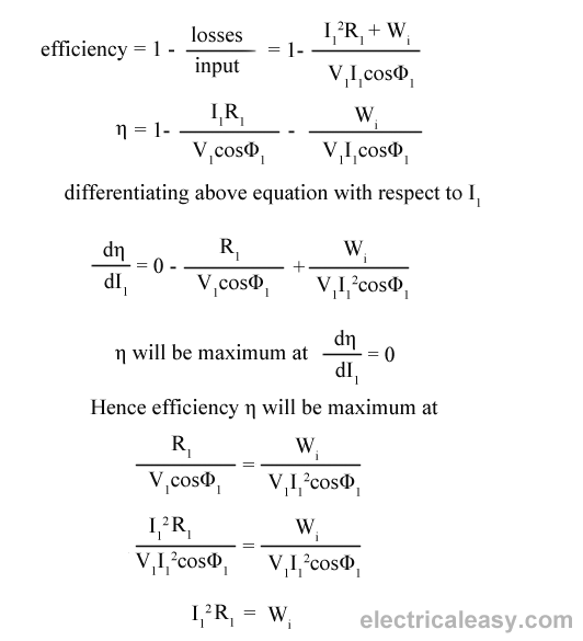
Transformers are the most highly efficient electrical devices. Most of the transformers have full load efficiency between 95% to 98.5% . As a transformer being highly efficient, output and input are having nearly same value, and hence it is impractical to measure the efficiency of transformer by using output / input. A better method to find efficiency of a transformer is using, efficiency = (input - losses) / input = 1 - (losses / input).

Condition for maximum efficiency

Let,
Copper loss = I12R1
Iron loss = Wi
efficiency of transformer
Hence, efficiency of a transformer will be maximum when copper loss and iron losses are equal.
That is Copper loss = Iron loss.

All day efficiency of transformer

As we have seen above, ordinary or commercial efficiency of a transformer can be given as
efficiency of transformer
But in some types of transformers, their performance can not be judged by this efficiency. For example, distribution transformers have their primaries energized all the time. But, their secondaries supply little load all no-load most of the time during day (as residential use of electricity is observed mostly during evening till midnight).
That is, when secondaries of transformer are not supplying any load (or supplying only little load), then only core losses of transformer are considerable and copper losses are absent (or very little). Copper losses are considerable only when transformers are loaded. Thus, for such transformers copper losses are relatively less important.  The performance of such transformers is compared on the basis of energy consumed in one day.
All day efficiency of a transformer is always less than ordinary efficiency of it.

Read More...

Transformer with resistance and leakage reactance

Magnetic leakage

magnetic leakage reactance transformer
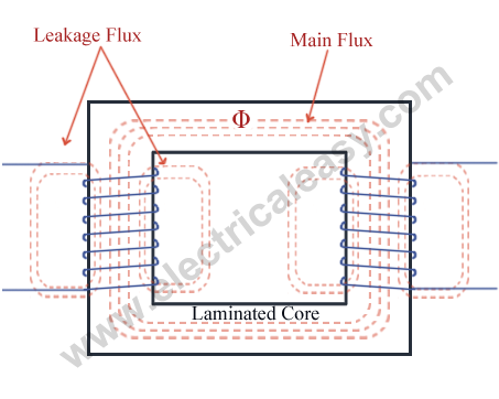
In a transformer it is observed that, all the flux linked with primary winding does not get linked with secondary winding. A small part of the flux completes its path through air rather than through the core (as shown in the fig at right), and this small part of flux is called as leakage flux or magnetic leakage in transformers. This leakage flux does not link with both the windings, and hence it does not contribute to transfer of energy from primary winding to secondary winding. But, it produces self induced emf in each winding. Hence, leakage flux produces an effect equivalent to an inductive coil in series with each winding. And due to this there will be leakage reactance.

(To minimize this leakage reactance, primary and secondary windings are not placed on separate legs, refer the diagram of core type and shell type transformer from construction of transformer.)

Practical Transformer with resistance and leakage reactance

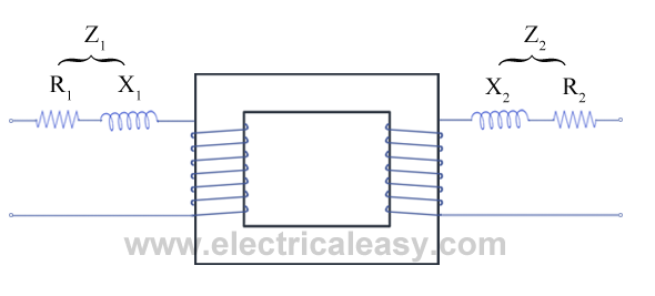
In the following figure, leakage reactance and resitance of the primary winding as well as secondary winding are taken out, representing a practical transformer.
transformer with resistance and leakage reactance
 Where, R1 and R2 = resistance of primary and secondary winding respectively
              X1 and X2 = leakage reactance of primary and secondary winding resp.
              Z1 and Z2 = Primary impedance and secondary impedance resp.
 Z1 = R1 + jX1 ...and Z2 = R2 + jX 2 .
The impedance in each winding lead to some voltage drop in each winding. Considering this voltage drop the voltage equation of transformer can be given as -
V1 = E1 + I1(R1 + jX1 ) --------primary side
V2 = E2 - I2(R2 + jX2 ) --------secondary side

where, V1 = supply voltage of primary winding
            V2 = terminal voltage of secondary winding
            E1 and E2 = induced emf in primary and secondary winding respectively. (EMF equation of a transformer.)


Read More...