Advertisements

Synchronous motor - construction and working

Synchronous motor and induction motor are the most widely used types of AC motor. Construction of a synchronous motor is similar to an alternator (AC generator). A same synchronous machine can be used as a synchronous motor or as an alternator. Synchronous motors are available in a wide range, generally rated between 150kW to 15MW with speeds ranging from 150 to 1800 rpm.

Construction of synchronous motor

construction of synchronous motor

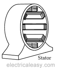
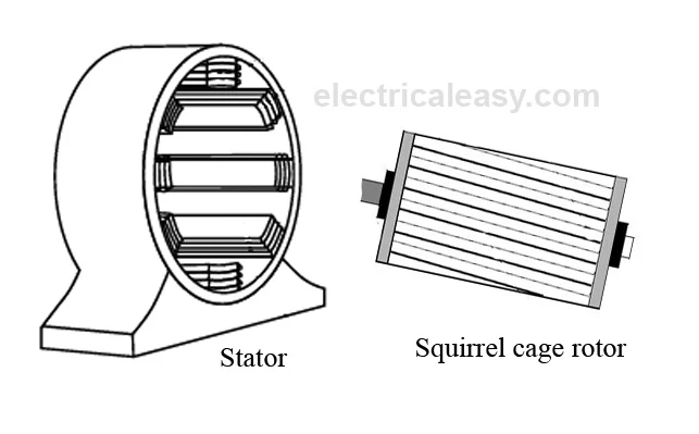
The construction of a synchronous motor (with salient pole rotor) is as shown in the figure at left. Just like any other motor, it consists of a stator and a rotor. The stator core is constructed with thin silicon lamination and insulated by a surface coating, to minimize the eddy current and hysteresis losses. The stator has axial slots inside, in which three phase stator winding is placed. The stator is wound with a three phase winding for a specific number of poles equal to the rotor poles. 
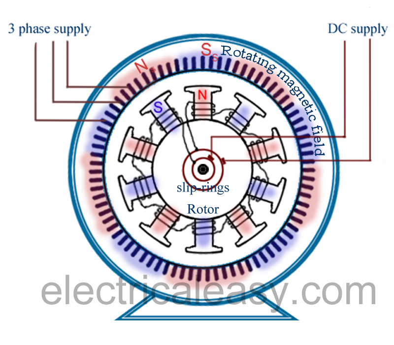
The rotor in synchronous motors is mostly of salient pole type. DC supply is given to the rotor winding  via slip-rings. The direct current excites the rotor winding and creates electromagnetic poles. In some cases permanent magnets can also be used. The figure above illustrates the construction of a synchronous motor very briefly.

Working of synchronous motor

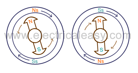
The stator is wound for the similar number of poles as that of rotor, and fed with three phase AC supply. The 3 phase AC supply produces rotating magnetic field in stator. The rotor winding is fed with DC supply which magnetizes the rotor. Consider a two pole synchronous machine as shown in figure below.
working of synchronous motor

  • Now, the stator poles are revolving with synchronous speed (lets say clockwise). If the rotor position is such that, N pole of the rotor is near the N pole of the stator (as shown in first schematic of above figure), then the poles of the stator and rotor will repel each other, and the torque produced will be anticlockwise.
  • The stator poles are rotating with synchronous speed, and they rotate around very fast and interchange their position. But at this very soon, rotor can not rotate with the same angle (due to inertia), and the next position will be likely the second schematic in above figure. In this case, poles of the stator will attract the poles of rotor, and the torque produced will be clockwise.
  • Hence, the rotor will undergo to a rapidly reversing torque, and the motor will not start.
But, if the rotor is rotated upto the synchronous speed of the stator by means of an external force (in the direction of revolving field of the stator), and the rotor field is excited near the synchronous speed, the poles of stator will keep attracting the opposite poles of the rotor (as the rotor is also, now, rotating with it and the position of the poles will be similar throughout the cycle). Now, the rotor will undergo unidirectional torque. The opposite poles of the stator and rotor will get locked with each other, and the rotor will rotate at the synchronous speed.

Characteristic features of a synchronous motor

  • Synchronous motor will run either at synchronous speed or will not run at all.
  • The only way to change its speed is to change its supply frequency. (As Ns = 120f / P)
  • Synchronous motors are not self starting. They need some external force to bring them near to the synchronous speed.
  • They can operate under any power factor, lagging as well as leading. Hence, synchronous motors can be used for power factor improvement.

 Application of synchronous motor

  • As synchronous motor is capable of operating under either leading and lagging power factor, it can be used for power factor improvement.  A synchronous motor under no-load with leading power factor is connected in power system where static capacitors can not be used.
  • It is used where high power at low speed is required. Such as rolling mills, chippers, mixers, pumps, pumps, compressor etc.

Read More...

Double squirrel cage motor

Squirrel cage motors are the most commonly used induction motors, but the main drawback in them is their poor starting torque due to low rotor resistance. (Starting torque is directly proportional to the rotor resistance). But increasing the rotor resistance for improving starting torque is not advisory as it will reduce the efficiency of the motor (due to more copper loss). One can not even add external resistance for starting of purposes, as the rotor bars are permanently short circuited (Construction of a squirrel cage rotor is here). These drawbacks are removed by a double squirrel cage motor, which has high starting torque without sacrificing efficiency.

Construction of double squirrel cage rotor

double squirrel cage motor rotor
cross section of double squirrel cage rotor
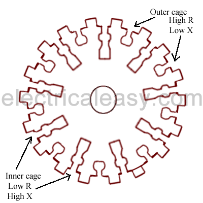
Rotor of a double squirrel cage motor has two independent cages on the same rotor. The figure at left shows the cross sectional diagram of a double squirrel cage rotor.
Bars of high resistance and low reactance are placed in the outer cage, and bars of low resistance and high reactance are placed in the inner cage. The outer cage has high 'reactance to resistance ratio' whereas, the inner cage has low 'reactance to resistance ratio'.

Working of double squirrel cage motor

At starting of the motor, frequency of induced emf is high because of large slip (slip = frequency of rotor emf / supply frequency). Hence the reactance of inner cage (2πfL    where, f = frequency of rotor emf) will be very high, increasing its total impedance. Hence at starting most of the current flows through outer cage despite its large resistnace (as total impedance is lower than the inner cage). This will not affect the outer cage because of its low reactance. And because of the large resistance of outer cage starting torque will be large.
As speed of the motor increases, slip decreases, and hence the rotor frequency decreases. In this case, the reactance of inner cage will be low, and most of the current will flow through the inner cage which is having low resistance. Hence giving a good efficiency.
When the double cage motor is running at normal speed, frequency of the rotor emf is so low that the reactance of both cages is negligible. The two cages being connected in parallel, the combined resistance is lower.
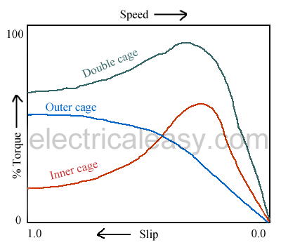
The torque speed characteristics of double squirrel cage motor for both the cages are shown in the figure below.
  
speed torque characteristics double squirrel cage motor

Read More...

Universal Motor - construction, working and characteristics

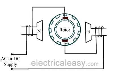
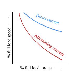
A universal motor is a special type of motor which is designed to run on either DC or single phase AC supply. These motors are generally series wound (armature and field winding are in series), and hence produce high starting torque (See characteristics of DC motors here). That is why, universal motors generally comes built into the device they are meant to drive. Most of the universal motors are designed to  operate at higher speeds, exceeding 3500 RPM. They run at lower speed on AC supply than they run on DC supply of same voltage, due to the reactance voltage drop which is present in AC and not in DC.
There are two basic types of universal motor : (i)compensated type and (ii) uncompensated type

Construction of Universal motor

construction of universal motor
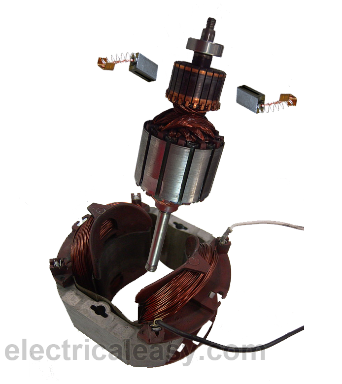
Construction of a universal motor is very similar to the construction of a DC machine. It consists of a stator on which field poles are mounted. Field coils are wound on the field poles.
However, the whole magnetic path (stator field circuit and also armature) is laminated. Lamination is necessary to minimize the eddy currents which induce while operating on AC.
The rotary armature is of wound type having straight or skewed slots and commutator with brushes resting on it. The commutation on AC is poorer than that for DC. because of the current induced in the armature coils. For that reason brushes used are having high resistance.


Working of universal motor

universal motor
A universal motor works on either DC or single phase AC supply. When the universal motor is fed with a DC supply, it works as a DC series motor. (see working of a DC series motor here). When current flows in the field winding, it produces an electromagnetic field. The same current also flows from the armature conductors. When a current carrying conductor is placed in an electromagnetic field, it experiences a mechanical force. Due to this mechanical force, or torque, the rotor starts to rotate. The direction of this force is given by Fleming's left hand rule.

When fed with AC supply, it still produces unidirectional torque. Because, armature winding and field winding are connected in series, they are in same phase. Hence, as polarity of AC changes periodically, the direction of current in armature and field winding reverses at the same time.
Thus, direction of magnetic field and the direction of armature current reverses in such a way that the direction of force experienced by armature conductors remains same. Thus, regardless of AC or DC supply, universal motor works on the same principle that DC series motor works.

Speed/load characteristics

speed load characteristics universal motor
Speed/load characteristics of a universal motor is similar to that of DC series motor. The speed of a universal motor is low at full load and very high at no load. Usually, gears trains are used to get the required speed on required load. The speed/load characteristics are (for both AC as well as DC supply) are shown in the figure.

Applications of universal motor

  • Universal motors find their use in various home appliances like vacuum cleaners, drink and food mixers, domestic sewing machine etc.
  • The higher rating universal motors are used in portable drills, blenders etc.

Read More...

Single Phase Motor schematics and working

Single phase motors are very widely used in home, offices, workshops etc. as power delivered to most of the houses and offices is single phase. In addition to this, single phase motors are reliable, cheap in cost, simple in construction and easy to repair. 
Single phase electric motors can be classified as:
  1. Single phase induction motor (Split phase, Capacitor and shaded pole etc)
  2. Single phase synchronous motor
  3. Repulsion motor etc.
 This article explains the basic construction and working of single phase induction motor.

Single phase Induction motor

single phase induction motor schematic
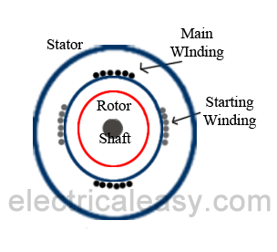
Construction of a single phase induction motor is similar to the construction of three phase induction motor having squirrel cage rotor, except that the stator is wound for single phase supply. Stator is also provided with a 'starting winding' which is used only for starting purpose. This can be understood from the schematic of single phase induction motor at the left.

Working principle of single phase induction motor

When the stator of a single phase motor is fed with single phase supply, it produces alternating flux in the stator winding.  The alternating current flowing through stator winding causes induced current in the rotor bars (of the squirrel cage rotor ) according to Faraday's law of electromagnetic induction. This induced current in the rotor will also produce alternating flux. Even after both alternating fluxes are set up, the motor fails to start (the reason is explained below). However, if the rotor is given a initial start by external force in either direction, then motor accelerates to its final speed and keeps running with its rated speed. This behavior of a single phase motor can be explained by double-field revolving theory.

Double-field revolving theory

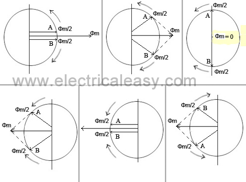
The double-field revolving theory states that, any alternating quantity (here, alternating flux) can be resolved into two components having magnitude half of the maximum magnitude of the alternating quantity, and both these components rotating in opposite direction.
Following figures will help you understanding the double field revolving theory.
double revolving field theory

Why single phase induction motor is not self starting?

The stator of a single phase induction motor is wound with single phase winding. When the stator is fed with a single phase supply, it produces alternating flux (which alternates along one space axis only). Alternating flux acting on a squirrel cage rotor can not produce rotation, only revolving flux can. That is why a single phase induction motor is not self starting.

How to make single phase induction motor self starting?

  • As explained above, single phase induction motor is not self-starting. To make it self-starting, it can be temporarily converted into a two-phase motor while starting. This can be achieved by introducing an additional 'starting winding' also called as auxillary winding.
  • Hence, stator of a single phase motor has two windings: (i) Main winding and (ii) Starting winding (auxillary winding). These two windings are connected in parallel across a single phase supply and are spaced 90 electrical degrees apart. Phase difference of 90 degree can be achieved by connecting a capacitor in series with the starting winding. 
  • Hence the motor behaves like a two-phase motor and the stator produces revolving magnetic field which causes rotor to run. Once motor gathers speed, say upto 80 or 90% of its normal speed, the starting winding gets disconnected form the circuit by means of a centrifugal switch, and the motor runs only on main winding.

Read More...

Starting methods of three phase induction motors

An induction motor is similar to a poly-phase transformer whose secondary is short circuited. Thus, at normal supply voltage, like in transformers, the initial current taken by the primary is very large for a short while. Unlike in DC motors, large current at starting is due to the absence of back emf. If an induction motor is directly switched on from the supply, it takes 5 to 7 times its full load current and develops a torque which is only 1.5 to 2.5 times the full load torque. This large starting current produces a large voltage drop in the line, which may affect the operation of other devices connected to the same line. Hence, it is not advisable to start induction motors of higher ratings (generally above 25kW) directly from the mains supply.
Various starting methods of induction motors are described below.

Direct-on-line (DOL) starters

Small three phase induction motors can be started direct-on-line, which means that the rated supply is directly applied to the motor. But, as mentioned above, here, the starting current would be very large, usually 5 to 7 times the rated current. The starting torque is likely to be 1.5 to 2.5 times the full load torque. Induction motors can be started directly on-line using a DOL starter which generally consists of a contactor and a motor protection equipment such as a circuit breaker. A DOL starter consists of a coil operated contactor which can be controlled by start and stop push buttons. When the start push button is pressed, the contactor gets energized and it closes all the three phases of the motor to the supply phases at a time. The stop push button de-energizes the contactor and disconnects all the three phases to stop the motor.
In order to avoid excessive voltage drop in the supply line due to large starting current, a DOL starter is generally used for motors that are rated below 5kW.

Starting of squirrel cage motors

Starting in-rush current in squirrel cage motors is controlled by applying reduced voltage to the stator. These methods are sometimes called as reduced voltage methods for starting of squirrel cage induction motors. For this purpose, following methods are used:
  1. By using primary resistors
  2. Autotransformer
  3. Star-delta switches

1. Using primary resistors:

primary resistors starting of induction motor
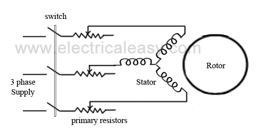
Obviously, the purpose of primary resistors is to drop some voltage and apply a reduced voltage to the stator. Consider, the starting voltage is reduced by 50%. Then according to the Ohm's law (V=I/Z), the starting current will also be reduced by the same percentage. From the torque equation of a three phase induction motor, the starting torque is approximately proportional to the square of the applied voltage. That means, if the applied voltage is 50% of the rated value, the starting torque will be only 25% of its normal voltage value. This method is generally used for a smooth starting of small induction motors. It is not recommended to use primary resistors type of starting method for motors with high starting torque requirements.
Resistors are generally selected so that 70% of the rated voltage can be applied to the motor. At the time of starting, full resistance is connected in the series with the stator winding and it is gradually decreased as the motor speeds up. When the motor reaches an appropriate speed, the resistances are disconnected from the circuit and the stator phases are directly connected to the supply lines.

2. Auto-transformers:

auto transformer starting of induction motors
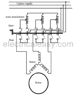
Auto-transformers are also known as auto-starters. They can be used for both star connected or delta connected squirrel cage motors. It is basically a three phase step down transformer with different taps provided that permit the user to start the motor at, say, 50%, 65% or 80% of line voltage. With auto-transformer starting, the current drawn from supply line is always less than the motor current by an amount equal to the transformation ratio. For example, when a motor is started on a 65% tap, the applied voltage to the motor will be 65% of the line voltage and the applied current will be 65% of the line voltage starting value, while the line current will be 65% of 65% (i.e. 42%) of the line voltage starting value. This difference between the line current and the motor current is due to transformer action. The internal connections of an auto-starter are as shown in the figure. At starting, switch is at "start" position, and a reduced voltage (which is selected using a tap) is applied across the stator. When the motor gathers an appropriate speed, say upto 80% of its rated speed, the auto-transformer automatically gets disconnected from the circuit as the switch goes to "run" position.
The switch changing the connection from start to run position may be air-break (small motors) or oil-immersed (large motors) type. There are also provisions for no-voltage and overload, with time delay circuits on an autostarter.

3. Star-delta starter:

This method is used in the motors, which are designed to run on delta connected stator. A two way switch is used to connect the stator winding in star while starting and in delta while running at normal speed. When the stator winding is star connected, voltage over each phase in motor will be reduced by a factor 1/(sqrt. 3) of that would be for delta connected winding. The starting torque will 1/3 times that it will be for delta connected winding. Hence a star-delta starter is equivalent to an auto-transformer of ratio 1/(sqrt. 3) or 58% reduced voltage.

Starting of slip-ring motors

starting of slip ring motor
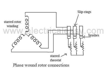
Slip-ring motors are started with full line voltage, as external resistance can be easily added in the rotor circuit with the help of slip-rings. A star connected rheostat is connected in series with the rotor via slip-rings as shown in the fig. Introducing resistance in rotor current will decrease the starting current in rotor (and, hence, in stator). Also, it improves power factor and the torque is increased. The connected rheostat may be hand-operated or automatic.
As, introduction of additional resistance in rotor improves the starting torque, slip-ring motors can be started on load.
The external resistance introduced is only for starting purposes, and is gradually cut out as the motor gathers the speed.
Read More...

Crawling and Cogging in Induction Motors

Crawling and cogging both are particularly related to squirrel cage induction motors.

Crawling

Sometimes, squirrel cage induction motors exhibits a tendency to run at very slow speeds (as low as one-seventh of their synchronous speed). This phenomenon is called as crawling of an induction motor.
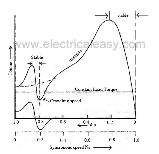
This action is due to the fact that, flux wave produced by a stator winding is not purely sine wave. Instead, it is a complex wave consisting a fundamental wave and odd harmonics like 3rd, 5th, 7th etc. The fundamental wave revolves synchronously at synchronous speed Ns whereas 3rd, 5th, 7th harmonics may rotate in forward or backward direction at Ns/3, Ns/5, Ns/7 speeds respectively. Hence, harmonic torques are also developed in addition with fundamental torque.
3rd harmonics are absent in a balanced 3-phase system. Hence 3rdd harmonics do not produce rotating field and torque. The total motor torque now consist three components as: (i) the fundamental torque with synchronous speed Ns, (ii) 5th harmonic torque with synchronous speed Ns/5, (iv) 7th harmonic torque with synchronous speed Ns/7 (provided that higher harmonics are neglected).
crawling in induction motot
Now, 5th harmonic currents will have phase difference of 5 X 120 =  600° =2 X 360 - 120 = -120°. Hence the revolving speed set up will be in reverse direction with speed Ns/5. The small amount of 5th harmonic torque produces breaking action and can be neglected.
The 7th harmonic currents will have phase difference of 7 X 120 = 840° = 2 X 360 +120 = + 120°. Hence they will set up rotating field in forward direction with synchronous speed equal to Ns/7. If we neglect all the higher harmonics, the resultant torque will be equal to sum of fundamental torque and 7th harmonic torque. 7th harmonic torque reaches its maximum positive value just before1/7 th of Ns. If the mechanical load on the shaft involves constant load torque, the torque developed by the motor may fall below this load torque. In this case, motor will not accelerate upto its normal speed, but it will run at a speed which is nearly 1/7th of of its normal speed. This phenomenon is called as crawling in induction motors.

Cogging (Magnetic locking or teeth locking)

Sometimes, the rotor of a squirrel cage induction motor refuses to start at all, particularly if the supply voltage is low. This happens especially when number of rotor teeth is equal to number of stator teeth, because of magnetic locking between the stator teeth and the rotor teeth. When the rotor teeth and stator teeth face each other, the reluctance of the magnetic path is minimum, that is why the rotor tends to remain fixed. This phenomenon is called cogging or magnetic locking of induction motor.

Read More...

Standard types of squirrel cage motors

Squirrel cage motors are standardized into different types according to their electrical characteristics. These standard types are called as class A, B, C, D, E and F respectively. Class A motors are referred as 'normal starting torque, normal starting-current, normal slip' and are used as reference motors.
Standard types of squirrel cage motors are as explained below:

(i) Class A  - (Normal starting torque, normal starting current, normal slip)

Class A is the most popular type of squirrel cage induction motor. Motors of this type employ squirrel cage having relatively low resistance and reactance. Its blocked-rotor current (with full voltage) is generally more than 6 times rated full load current. For smaller size and less number of poles, starting torque with full load voltage is nearly twice the full load torque.For larger size and more number of poles starting torque is only a bit more than full load torque. The full load slip is less than 5%.   The rotor bars are placed close the the rotor surface to reduce the rotor reactance.
Class A motors are used in fans, compressors, pumps, conveyors etc. which are having low inertia loads so that the motor can accelerate in less time.

(ii) Class B - (Normal starting torque, low starting current, normal slip)
Class B motors can be started at full load, developing normal starting torque with relatively low starting current. Their blocked-rotor current with full voltage is generally 5 times the full load current. Rotor bars are narrow and placed deeper to obtain high reactance at starting.
These motors are used where load is having high inertia, e.g large fans, machine tools applications, for driving electric generators, centrifugal pumps etc.

(iii) Class C
- (high starting torque, low starting current, normal slip)
Class C motors are generally double squirrel cage type. Their blocked-rotor current and slip with full voltage is nearly similar to that of class B motors. Their starting torque with full applied voltage is genrally about three times the full load torque.
These motors are used where sufficiently high starting torque with reduced starting voltage is reqired. They are used for crushers, compression pumps, large refrigerators, textile machinery, wood working eqipment etc.

(iv) Class D - (high starting torque, low starting current, high slip)
In class D motors rotor bars of high resistance are used so as to give high starting torque with low starting current. Their blocked rotor current with full applied voltage is similar to that of class B or class C motors. Full load slip may vary from 5% to 20% depending upon application. Thin rotor bars are used which reduces the leakage flux and increases the useful flux, thus giving high starting torque with low starting current.
These motors are used where extremely high starting torque is required. E.g. bulldozers, shearing machines, foundry equipment, punch presses, stamping machines, metal drawing equipment, laundry equipment etc.

(v) Class E - (low starting torque, normal starting current, low slip)
Class E motors are having relatively low slip at rated load. For motors above 5kW rating, starting current may be high, so they require compensator or resistance starter.

(vi) Class F - (low starting torque, low starting current, normal slip)
As these motors are having low starting torque with low starting current, they can be started at full voltage. The rotor is designed such that it gives high reactance at starting. The blocked rotor current and full load slip with full applied voltage is similar to that of class B or class C motors. The starting torque with full applied voltage is nearly 1.25 times the full load torque.
Read More...

Speed control methods of induction motor

An induction motor is practically a constant speed motor, that means, for the entire loading range, change in speed of the motor is quite small. Speed of a DC shunt motor can be varied very easily with good efficiency, but in case of Induction motors, speed reduction is accompanied by a corresponding loss of efficiency and poor power factor. As induction motors are widely being used, their speed control may be required in many applications. Different speed control methods of induction motor are explained below.

Induction motor speed control from stator side

1. By changing the applied voltage:

From the torque equation of induction motor,
torque equation of an induction motor
Rotor resistance R2 is constant and if slip s is small then (sX2)2 is so small that it can be neglected. Therefore, T ∝ sE22 where E2 is rotor induced emf and E2 V
Thus, T ∝ sV2,  which means, if supplied voltage is decreased, the developed torque decreases. Hence, for providing the same load torque, the slip increases with decrease in voltage, and consequently, the speed decreases. This method is the easiest and cheapest, still rarely used, because
  1. large change in supply voltage is required for relatively small change in speed.
  2. large change in supply voltage will result in a large change in flux density, hence, this will disturb the magnetic conditions of the motor.

2. By changing the applied frequency

Synchronous speed of the rotating magnetic field of an induction motor is given by,
synchronous speed of an induction motor
where, f = frequency of the supply and P = number of stator poles.
Hence, the synchronous speed changes with change in supply frequency. Actual speed of an induction motor is given as N = Ns (1 - s). However, this method is not widely used. It may be used where, the induction motor is supplied by a dedicated generator (so that frequency can be easily varied by changing the speed of prime mover). Also, at lower frequency, the motor current may become too high due to decreased reactance. And if the frequency is increased beyond the rated value, the maximum torque developed falls while the speed rises.

3. Constant V/F control of induction motor

This is the most popular method for controlling the speed of an induction motor. As in above method, if the supply frequency is reduced keeping the rated supply voltage, the air gap flux will tend to saturate. This will cause excessive stator current and distortion of the stator flux wave. Therefore, the stator voltage should also be reduced in proportional to the frequency so as to maintain the air-gap flux constant. The magnitude of the stator flux is proportional to the ratio of the stator voltage and the frequency. Hence, if the ratio of voltage to frequency is kept constant, the flux remains constant. Also, by keeping V/F constant, the developed torque remains approximately constant. This method gives higher run-time efficiency. Therefore, majority of AC speed drives employ constant V/F method (or variable voltage, variable frequency method) for the speed control. Along with wide range of speed control, this method also offers 'soft start' capability.

4. Changing the number of stator poles

From the above equation of synchronous speed, it can be seen that synchronous speed (and hence, running speed) can be changed by changing the number of stator poles. This method is generally used for squirrel cage induction motors, as squirrel cage rotor adapts itself for any number of stator poles. Change in stator poles is achieved by two or more independent stator windings wound for different number of poles in same slots.
For example, a stator is wound with two 3phase windings, one for 4 poles and other for 6 poles.
for supply frequency of 50 Hz
i) synchronous speed when 4 pole winding is connected, Ns = 120*50/4 = 1500 RPM
ii) synchronous speed when 6 pole winding is connected, Ns = 120*50/6 = 1000 RPM

Speed control from rotor side:

1. Rotor rheostat control

This method is similar to that of armature rheostat control of DC shunt motor. But this method is only applicable to slip ring motors, as addition of external resistance in the rotor of squirrel cage motors is not possible.

2. Cascade operation

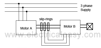
In this method of speed control, two motors are used. Both are mounted on a same shaft so that both run at same speed. One motor is fed from a 3phase supply and the other motor is fed from the induced emf in first motor via slip-rings. The arrangement is as shown in following figure.
cascade operation speed control of induction motor
Motor A is called the main motor and motor B is called the auxiliary motor.
Let, Ns1 = frequency of motor A
       Ns2 = frequency of motor B
       P1 = number of poles stator of motor A
       P2 = number of stator poles of motor B
       N = speed of the set and same for both motors
       f = frequency of the supply

Now, slip of motor A, S1 = (Ns1 - N) / Ns1.
frequency of the rotor induced emf in motor A,   f1 = S1f
Now, auxiliary motor B is supplied with the rotor induce emf

therefore,  Ns2 = (120f1) / P2  =  (120S1f) / P2.

now putting the value of  S1 = (Ns1 - N) / Ns1
 At no load, speed of the auxiliary rotor is almost same as its synchronous speed.
i.e. N = Ns2.
from the above equations, it can be obtained that
With this method, four different speeds can be obtained
1. when only motor A works, corresponding speed = .Ns1 = 120f / P1
2. when only motor B works, corresponding speed = Ns2 = 120f / P2
3. if commulative cascading is done, speed of the set = N = 120f / (P1 + P2)
4. if differential cascading is done, speed of the set = N = 120f (P1 - P2)

3. By injecting EMF in rotor circuit

In this method, speed of an induction motor is controlled by injecting a voltage in rotor circuit. It is necessary that voltage (emf) being injected must have same frequency as of the slip frequency. However, there is no restriction to the phase of injected emf. If we inject emf which is in opposite phase with the rotor induced emf, rotor resistance will be increased. If we inject emf which is in phase with the rotor induced emf, rotor resistance will decrease. Thus, by changing the phase of injected emf, speed can be controlled. The main advantage of this method is a wide rage of speed control (above normal as well as below normal) can be achieved. The emf can be injected by various methods such as Kramer system, Scherbius system etc.
Read More...

Torque equation of three phase induction motor

Torque of a three phase induction motor is proportional to flux per stator pole, rotor current and the power factor of the rotor.

T   ɸ I2 cosɸ2      OR      T = k ɸ I2 cosɸ2 .
where, ɸ = flux per stator pole,
            I2 = rotor current at standstill,
            ɸ = angle between rotor emf and rotor current,
             k = a constant.

Now, let E2 = rotor emf at standstill
we know, rotor emf is directly proportional to flux per stator pole, i.e. E2 ɸ.
therefore,  T E2 I2 cosɸ       OR      T =k1 E2 I2 cosɸ2.

Starting torque

The torque developed at the instant of starting of a motor is called as starting torque. Starting torque may be greater than running torque in some cases, or it may be lesser.
We know, T =k1 E2 I2 cosɸ2.

let, R2 = rotor resistance per phase
      X2 = standstill rotor reactance

  
 then,
Therefore, starting torque can be given as,
The constant k1 = 3 / 2πNs

 Condition for maximum starting torque

If supply voltage V is kept constant, then flux ɸ and E2 both remains constant. Hence,
Hence, it can be proved that maximum starting torque is obtained when rotor resistance is equal to standstill rotor reactance. i.e. R22 + X22 =2R22 .

 Torque under running condition

T  ɸ Ir cosɸ2 .
where, Er = rotor emf per phase under running condition = sE2.  (s=slip)
            Ir = rotor current per phase under running condition
reactance per phase under running condition will be  = sX2
therefore,
 as, ɸ ∝ E2.

Maximum torque under running condition

Torque under running condition is maximum at the value of slip (s) which makes rotor reactance per phase equal to rotor resistance per phase.

Read More...

Production of rotating magnetic field in polyphase stator


In an induction motor, when AC supply is given to the the stator, magnetic flux is produced which is revolving at synchronous speed. This post will explain you in brief about production of rotating magnetic flux for 2 phase as well as 3 phase supply.

For 2 phase supply:

two phase revolving magnetic field
fig (a)
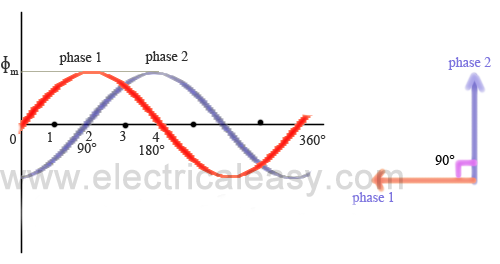
Let the stator is wound for 2 phase supply. The two phases are kept 90 space degrees apart as illustrated in fig (a).

Let, Φ1 and  Φ2 be the instantaneous values of the fluxes set up by phase 1 and phase 2 respectively.

revolving magnetic flux two phase

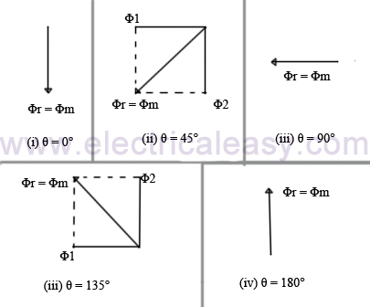
(i) When θ = 0° (at origin fig. a), magnitude of the flux set up by phase-1 will be 0 and the magnitude of the flux by phase 2 will be maximum but in negative direction. This is illustrated in fig (b). Hence the magnitude of the resultant flux Φr will be equal to Φm.

(ii) θ = 45° (position 1 in fig a)
Flux by phase-1 >> Φ1 = sqrt.2 * Φm.
Flux by phase-2  >> Φ2 = sqrt.2 * Φm.
Hence resultant flux >> Φr = Φm.
But the resultant has shifted 45 degrees clockwise.

(iii) θ = 90° (position 2)
Flux by phase-1 >> Φ1 = Φm.
Flux by phase-2  >> Φ2 = 0.
Hence resultant flux >> Φr = Φm.
But the resultant has further shifted 45 degrees clockwise OR resultant has shifted 90 degrees from its initial position.

(iv) θ = 135° (position 3)
Flux by phase-1 >> Φ1 = Φm.
Flux by phase-2  >> Φ2 = Φm.
Hence resultant flux >> Φr = Φm.
But the resultant has further shifted 45 degrees clockwise OR resultant has shifted 135 degrees from its initial position.

(iv) θ = 180° (position 4)
Flux by phase-1 >> Φ1 = 0.
Flux by phase-2  >> Φ2 = Φm.
Hence resultant flux >> Φr = Φm.
But the resultant has further shifted 45 degrees clockwise OR resultant has shifted 180 degrees from its initial position.
Thus, it can be concluded that the magnitude of the resultant flux remains constant but its direction keeps rotating clockwise.

The speed of the rotating magnetic flux is called as synchronous speed (Ns) and it is given by
where, f =frequency of the supply and  P = number of poles.

3 Phase supply:

Similarly, for a three phase supply, following figures will illustrate.


rotating magnetic field 3 phase

Read More...

Three Phase Induction Motor

A three phase induction motor runs on a three phase AC supply. 3 phase induction motors are extensively used for various industrial applications because of their following advantages -
  • They have very simple and rugged (almost unbreakable) construction
  • they are very reliable and having low cost
  • they have high efficiency and good power factor
  • minimum maintenance required
  • 3 phase induction motor is self starting hence extra starting motor or any special starting arrangement is not required
They also have some disadvantages
  • speed decreases with increase in load, just like a DC shunt motor
  • if speed is to be varied, we have sacrifice some of its efficiency

Construction of a 3 phase induction motor

Just like any other motor, a 3 phase induction motor also consists of a stator and a rotor. Basically there are two types of 3 phase IM - 1. Squirrel cage induction motor and 2. Phase Wound induction motor (slip-ring induction motor). Both types have similar constructed rotor, but they differ in construction of rotor. This is explained further
.
Stator
stator of induction motor

The stator of a 3 phase IM (Induction Motor) is made up with number of stampings, and these stampings are slotted to receive the stator winding. The stator is wound with a 3 phase winding which is fed from a 3 phase supply. It is wound for a defined number of poles, and the number of poles is determined from the required speed. For greater speed, lesser number of poles is used and vice versa. When stator windings are supplied with 3 phase ac supply, they produce alternating flux which revolves with synchronous speed. The synchronous speed is inversely proportional to number of poles (Ns = 120f / P). This revolving or rotating magnetic flux induces current in rotor windings according to Faraday's law of mutual induction.


Rotor
As described earlier, rotor of a 3 phase induction motor can be of either two types, squirrel cage rotor and phase wound rotor (or simply - wound rotor).

Squirrel cage rotor

squirrel cage rotor
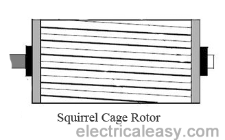
Most of the induction motors (upto 90%) are of squirrel cage type. Squirrel cage type rotor has very simple and almost indestructible construction. This type of rotor consist of a cylindrical laminated core, having parallel slots on it. These parallel slots carry rotor conductors. In this type of rotor, heavy bars of copper, aluminum or alloys are used as rotor conductors instead of wires.
Rotor slots are slightly skewed to achieve following advantages -
1. it reduces locking tendency of the rotor, i.e. the tendency of rotor teeth to remain under stator teeth due to magnetic attraction.
2. increases the effective transformation ratio between stator and rotor
3. increases rotor resistance due to increased length of the rotor conductor

The rotor bars are brazed or electrically welded to short circuiting end rings at both ends. Thus this rotor construction looks like a squirrel cage and hence we call it. The rotor bars are permanently short circuited, hence it is not possible to add any external resistance to armature circuit.

Phase wound rotor


phase wound rotor and slip ringsPhase wound rotor is wound with 3 phase, double layer, distributed winding. The number of poles of rotor are kept same to the number of poles of the stator. The rotor is always wound 3 phase even if the stator is wound two phase.
The three phase rotor winding is internally star connected. The other three terminals of the winding are taken out via three insulated sleep rings mounted on the shaft and the brushes resting on them. These three brushes are connected to an external star connected rheostat. This arrangement is done to introduce an external resistance in rotor circuit for starting purposes and for changing the speed / torque characteristics.
When motor is running at its rated speed, slip rings are automatically short circuited by means of a metal collar and brushes are lifted above the slip rings to minimize the frictional losses.

Read More...

Working principle and types of an Induction Motor

Induction Motors are the most commonly used motors in many applications. These are also called as Asynchronous Motors, because an induction motor always runs at a speed lower than synchronous speed. Synchronous speed means the speed of the rotating magnetic field in the stator.

There basically 2 types of induction motor depending upon the type of input supply - (i) Single phase induction motor and (ii) Three phase induction motor.

Or they can be divided according to type of rotor - (i) Squirrel cage motor and (ii) Slip ring motor or wound type

induction motor

Basic working principle of an Induction Motor

In a DC motor, supply is needed to be given for the stator winding as well  as the rotor winding. But in an induction motor only the stator winding is fed with an AC supply.
  • Alternating flux is produced around the stator winding due to AC supply. This alternating flux revolves with synchronous speed. The revolving flux is called as "Rotating Magnetic Field" (RMF).
  • The relative speed between stator RMF and rotor conductors causes an induced emf in the rotor conductors, according to the Faraday's law of electromagnetic induction. The rotor conductors are short circuited, and hence rotor current is produced due to induced emf. That is why such motors are called as induction motors
    (This action is same as that occurs in transformers, hence induction motors can be called as rotating transformers.) 
  • Now, induced current in rotor will also produce alternating flux around it. This rotor flux lags behind the stator flux. The direction of induced rotor current, according to Lenz's law, is such that it will tend to oppose the cause of its production. 
  • As the cause of production of rotor current is the relative velocity between rotating stator flux and the rotor, the rotor will try to catch up with the stator RMF. Thus the rotor rotates in the same direction as that of stator flux to minimize the relative velocity. However, the rotor never succeeds in catching up the synchronous speed. This is the basic working principle of induction motor of either type, single phase of 3 phase. 

Synchronous speed:

 The rotational speed of the rotating magnetic field is called as synchronous speed.
Snchronous speed Ns=120f/P
where, f = frequency of the spply
            P = number of poles

Slip:

Rotor tries to catch up the synchronous speed of the stator field, and hence it rotates. But in practice, rotor never succeeds in catching up. If rotor catches up the stator speed, there wont be any relative speed between the stator flux and the rotor, hence no induced rotor current and no torque production to maintain the rotation. However, this won't stop the motor, the rotor will slow down due to lost of torque, the torque will again be exerted due to relative speed. That is why the rotor rotates at speed which is always less the synchronous speed.
The difference between the synchronous speed (Ns) and actual speed  (N) of the rotor is called as slip.
slip in induction motor


Read More...

Faraday's law and Lenz's law of electromagnetic induction

Faraday's laws of of electromagnetic induction explains the relationship between electric circuit and magnetic field. This law is the basic working principle of the most of the electrical motors, generators, transformers, inductors etc.


Faraday's first law:

Whenever a conductor is placed in a varying magnetic field an EMF gets induced across the conductor (called as induced emf), and if the conductor is a closed circuit then induced current flows through it.
Magnetic field can be varied by various methods -
1. By moving magnet
2. By moving the coil
3. By rotating the coil relative to magnetic field

Faraday's second law:

Faraday's second law of electromagnetic induction states that,  the magnitude of induced emf is equal to the rate of change of flux linkages with the coil. The flux linkages is the product of number of turns and the flux associated with the coil.

Formula of Faraday's law:

Consider the conductor is moving in magnetic field, then
flux linkage with the coil at initial position of the conductor = NΦ1     (Wb) (N is speed of the motor and Φ is flux)
flux linkage with the coil at final position of the conductor = NΦ2       (Wb)
change in the flux linkage from initial to final = N(Φ1 - Φ2)
let  Φ1 - Φ2 = Φ
therefore, change in the flux linkage = NΦ
and, rate of change in the flux linkage = NΦ/t
taking the derivative of RHS
rate of change of flux linkages = N (dΦ/dt)

According to Faraday's law of electromagnetic induction, rate of change of flux linkages is equal to the induced emf

So, E = N (dΦ/dt)    (volts)

Phenomenon of Mutual Induction

Alternating current flowing in a coil produces alternating magnetic field around it. When two or more coils are magnetically linked to each other, then an alternating current flowing through one  coil causes an induced emf across the other linked coils. This phenomenon is called as mutual induction.

Lenz's law

Lenz's  law of electromagnetic induction states that, when an emf is induced according to Faraday's law, the polarity (direction) of that induced emf is such that it opposes the cause of its production.

Thus, considering Lenz's law

E = -N (dΦ/dt)   (volts)

The negative sign shows that, the direction of the induced emf and the direction of change in magnetic fields have opposite signs.
Read More...