Advertisements

Starting methods of a DC motor

Basic operational voltage equation of a DC motor is given as
E = Eb + IaRa   and hence,     Ia = (E - Eb) / Ra
Now, when the motor is at rest, obviously, the back emf Eb = 0. Hence, armature current at the moment of starting can be given as Ia = E / Ra. In practical DC machines, armature resistance is basically very low, generally about 0.5 Ω. Therefore, a large current flows through the armature during starting. This current is large enough to damage the armature circuit.
Due to this excessive starting current -
  1. the fuses may blow out and the armature winding and/or commutator brush arrangement may get damaged.
  2. very high starting torque will be produced (as torque is directly proportional to the armature current), and this high starting torque may cause huge centrifugal force which may throw off the armature winding.
  3. other loads connected to the same source may experience a dip in the terminal voltage.
A large DC motor will pick up speed rather slowly due to its large rotor inertia. Hence, building up the back emf slowly causing the level of high starting current maintained for quite some time. This may cause severe damage. To avoid this, a suitable DC motor starter must be used. Very small dc motors, however, may be started directly by connecting them to the supply with the help of a contactor or a switch. It does not result in any harm because they gather speed quickly due to small rotor inertia. In this case, the large starting current will die down quickly because of the fast rise in the back emf.

DC motor starters

To avoid the above dangers while starting a DC motor, it is necessary to limit the starting current. So, a DC motor is started by using a starter. There are various types of dc motor starters, such as 3 point starter, 4 point starter, no-load release coil starter, thyristor controller starter etc.
The basic concept behind every DC motor starter is adding external resistance to the armature winding during starting.
From the followings, 3 point starters and 4 point starters are used for starting shunt wound motors and compound wound motors.

3 Point Starter
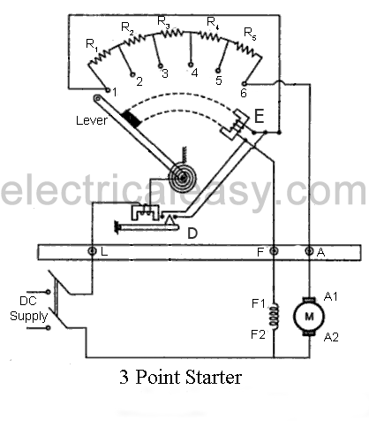
3 point starter The internal wiring of a 3 point starter is as shown in the figure.
When the connected dc motor is to be started, the lever is turned gradually to the right. When the lever touches point 1, the field winding gets directly connected across the supply, and the armature winding gets connected with resistances R1 to R5 in series. During starting, full resistance is added in series with the armature winding. Then, as the lever is moved further, the resistance is gradually is cut out from the armature circuit. Now, as the lever reaches to position 6, all the resistance is cut out from the armature circuit and armature gets directly connected across the supply. The electromagnet 'E' (no voltage coil) holds the lever at this position. This electromagnet releases the lever when there is no (or low) supply voltage.
It can be seen that, when the arm is moved from the position 1 to the last position, the starter resistance gets added in series with the field winding. But, as the value of starter resistance is very small as compared to the shunt resistance, the decrease in shunt field current may be negligible. However, to overcome this drawback a brass or copper arc may be employed within a 3 point starter which makes a connection between the moving arm and the field winding, as shown in the figure of 4 point starter below.
When the motor is overloaded beyond a predefined value, 'overcurrent release electromagnet' D gets activated, which short-circuits electromagnet E and, hence, releases the lever and the motor is turned off.

4 Point Starter
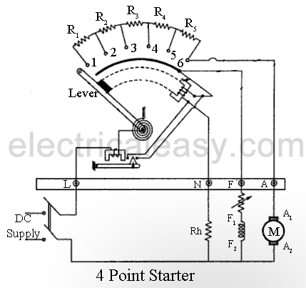
4 point starter The main difference between a 3 point starter and a 4 point starter is that the no voltage coil (electromagnet E) is not connected in series with the field coil. The field winding gets directly connected to the supply, as the lever moves touching the brass arc (the arc below the resistance studs). The no voltage coil (or Hold-on coil) is connected with a current limiting resistance Rh. This arrangement ensures that any change of current in the shunt field does not affect the current through hold-on coil at all. This means, electromagnetic pull of the hold-on coil will always be sufficient so that the spring does not unnecessarily restore the lever to the off position. A 4 point starter is used where field current is to be adjusted by means of a field rheostat for the purpose of operating the motor above rated speed by reducing the field current.

DC series motor starter

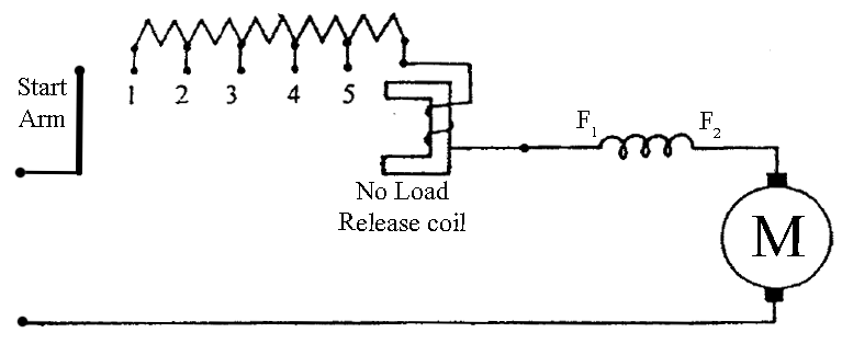
dc series motor starter or 2 point starter Construction of DC series motor starters is very basic as shown in the figure. The start arm is simply moved towards right to start the motor. Thus, maximum resistance is connected in series with the armature during starting and then gradually decreased as the start arm moves towards right. This starter is sometimes also called as a 2 point starter.
The no load release coil holds the start arm to the run position and leaves it when the voltage is lost.
Read More...

Electric braking of DC motors

A running motor may be brought to rest quickly by either mechanical braking or electrical braking. The mechanical braking is applied by means of mechanical break shoes. Hence the smoothness of mechanical braking is dependent on the surface and physical condition of brakes. Smooth braking of a motor can be achieved by electric braking.

Electric braking

The electric braking of a DC motor is of three types, (i) Rheostatic or dynamic braking, (ii) Plugging or reverse current braking  and (iii) Regenerative beaking.

(i) Rheostatic or dynamic braking:
In case of DC shunt motors, armature is disconnected from the supply and a rheostat (variable resistor) is connected across it. The field winding is left connected across the supply. Obviously, now armature is driven by the inertia and hence machine starts acting as a generator. Thus the machine will now feed the current to the connected rheostat and heat will dissipate at the rate of I2R. Braking effect is controlled by varying the resistance connected across the armature.
In case of DC series motor, motor is disconnected from the supply and field connections are reversed and a rheostat is connected in series. The field connections are reversed to make sure that the current through field winding will flow in the same direction as before.

(ii) Plugging or Reverse current braking:
In this method, armature connections are reversed and hence motor tends to run in opposite direction. Due to reversal of the armature terminals, applied voltage V and back emf Eb starts acting in the same direction and hence the total armature current exceeds. To limit this armature current a variable resistor is connected across the armature. This is similar for both series and shunt wound methods.
Plugging gives greater braking torque as compared to rheostatic braking. This method is generally used in controlling elevators, machine tools, printing presses etc.

(iii) Regenerative braking:
Regenerative braking is used where, load on the motor has very high inertia (e.g in electric trains). When applied voltage to the motor is reduced to less than back emf Eb, obviously armature current Ia will get reversed, and hence armature torque is reversed. Thus speed falls. As generated emf is greater than applied voltage (machine is acting as a DC generator), power will be returned to the line, this action is called as regeneration. Speed keeps falling, back emf Eb also falls until it becomes lower than applied voltage and direction of armature current again becomes opposite to Eb.
Read More...

Speed control methods of DC motor

Speed of a DC motor

Back emf Eb of a DC motor is nothing but the induced emf in armature conductors due to rotation of the armature in magnetic field. Thus, the magnitude of Eb can be given by EMF equation of a DC generator.
Eb = PØNZ/60A
(where, P = no. of poles, Ø = flux/pole, N = speed in rpm, Z = no. of armature conductors, A = parallel paths)

Eb can also be given as,
Eb = V- IaRa

thus, from the above equations
N = Eb 60A/PØZ

but, for a DC motor A, P and Z are constants

Therefore, N K Eb/Ø          (where, K=constant)

This shows the speed of a dc motor is directly proportional to the back emf and inversely proportional to the flux per pole.

Speed control methods of DC motor

Speed control of Shunt motor

1. Flux control method

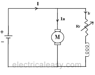
flux control method to control the speed of a dc shunt motor
It is already explained above that the speed of a dc motor is inversely proportional to the flux per pole. Thus by decreasing the flux, speed can be increased and vice versa.
To control the flux, a rheostat is added in series with the field winding, as shown in the circuit diagram. Adding more resistance in series with the field winding will increase the speed as it decreases the flux. In shunt motors, as field current is relatively very small, Ish2R loss is small. Therefore, this method is quite efficient. Though speed can be increased above the rated value by reducing flux with this method, it puts a limit to maximum speed as weakening of field flux beyond a limit will adversely affect the commutation.

2. Armature control method

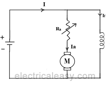
armature control method to control the speed of a shunt motor
Speed of a dc motor is directly proportional to the back emf Eb and Eb = V - IaRa. That means, when supply voltage V and the armature resistance Ra are kept constant, then the speed is directly proportional to armature current Ia. Thus, if we add resistance in series with the armature, Ia decreases and, hence, the speed also decreases. Greater the resistance in series with the armature, greater the decrease in speed.

3. Voltage Control Method

a) Multiple voltage control:
In this method, the shunt field is connected to a fixed exciting voltage and armature is supplied with different voltages. Voltage across armature is changed with the help of suitable switchgear. The speed is approximately proportional to the voltage across the armature.

b) Ward-Leonard System:
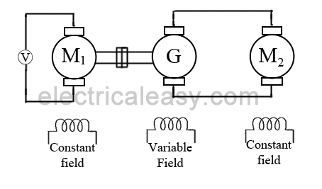
ward leonard system speed control of dc motor This system is used where very sensitive speed control of motor is required (e.g electric excavators, elevators etc.). The arrangement of this system is as shown in the figure at right.
M2 is the motor to which speed control is required.
M1 may be any AC motor or DC motor with constant speed.
G is a generator directly coupled to M1.
In this method, the output from generator G is fed to the armature of the motor M2 whose speed is to be controlled. The output voltage of generator G can be varied from zero to its maximum value by means of its field regulator and, hence, the armature voltage of the motor M2 is varied very smoothly. Hence, very smooth speed control of the dc motor can be obtained by this method.

Speed control of series motor

1. Flux control method

speed control of dc series motor
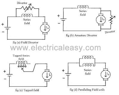
  • Field diverter: A variable resistance is connected parallel to the series field as shown in fig (a). This variable resistor is called as a diverter, as the desired amount of current can be diverted through this resistor and, hence, current through field coil can be decreased. Thus, flux can be decreased to the desired amount and speed can be increased.
  • Armature diverter: Diverter is connected across the armature as shown in fig (b).
    For a given constant load torque, if armature current is reduced then the flux must increase, as Ta ∝ ØIa
    This will result in an increase in current taken from the supply and hence flux Ø will increase and subsequently speed of the motor will decrease.
  • Tapped field control: As shown in fig (c) field coil is tapped dividing number of turns. Thus we can select different value of Ø by selecting different number of turns.
  • Paralleling field coils: In this method, several speeds can be obtained by regrouping coils as shown in fig (d).

2. Variable resistance in series with armature

By introducing resistance in series with the armature, voltage across the armature can be reduced. And, hence, speed reduces in proportion with it.

3. Series-parallel control

This system is widely used in electric traction, where two or more mechanically coupled series motors are employed. For low speeds, the motors are connected in series, and for higher speeds, the motors are connected in parallel.
When in series, the motors have the same current passing through them, although voltage across each motor is divided. When in parallel, the voltage across each motor is same although the current gets divided.
Read More...

How a DC motor works?

Theoretically, the same DC machine can be used as a motor or generator. Therefore, construction of a DC motor is same as that of a DC generator.

Working principle of a DC motor

An electric motor is an electrical machine which converts electrical energy into mechanical energy. The basic working principle of a DC motor is: "whenever a current carrying conductor is placed in a magnetic field, it experiences a mechanical force". The direction of this force is given by Fleming's left-hand rule and its magnitude is given by F = BIL. Where, B = magnetic flux density, I = current and L = length of the conductor within the magnetic field.

Fleming's left hand rule: If we stretch the first finger, second finger and thumb of our left hand to be perpendicular to each other, and the direction of magnetic field is represented by the first finger, direction of the current is represented by the second finger, then the thumb represents direction of the force experienced by the current carrying conductor.

working of dc motor animation
Animation: Working of DC Motor
(credit: Lookang)

Above animation helps in understanding the working principle of a DC motor. When armature windings are connected to a DC supply, an electric current sets up in the winding. Magnetic field may be provided by field winding (electromagnetism) or by using permanent magnets. In this case, current carrying armature conductors experience a force due to the magnetic field, according to the principle stated above.

Commutator is made segmented to achieve unidirectional torque. Otherwise, the direction of force would have reversed every time when the direction of movement of conductor is reversed in the magnetic field. This is how a DC motor works!

Back EMF

According to fundamental laws of nature, no energy conversion is possible until there is something to oppose the conversion. In case of generators this opposition is provided by magnetic drag, but in case of dc motors there is back emf.

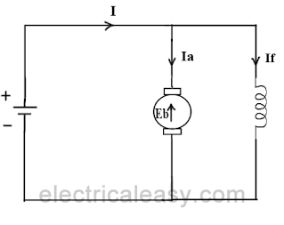
When the armature of a motor is rotating, the conductors are also cutting the magnetic flux lines and hence according to the Faraday's law of electromagnetic induction, an emf induces in the armature conductors. The direction of this induced emf is such that it opposes the armature current (Ia). The circuit diagram below illustrates the direction of the back emf and armature current. Magnitude of the Back emf can be given by emf equation of a DC generator.

back emf

Significance of back emf:

Magnitude of back emf is directly proportional to speed of the motor. Consider the load on a dc motor is suddenly reduced. In this case, required torque will be small as compared to the current torque. Speed of the motor will start increasing due to the excess torque. Hence, being proportional to the speed, magnitude of the back emf will also increase. With increasing back emf armature current will start decreasing. Torque being proportional to the armature current, it will also decrease until it becomes sufficient for the load. Thus, speed of the motor will regulate.

On the other hand, if a dc motor is suddenly loaded, the load will cause decrease in the speed. Due to decrease in speed, back emf will also decrease allowing more armature current. Increased armature current will increase the torque to satisfy the load requirement. Hence, presence of the back emf makes a dc motor ‘self-regulating’.

Types of DC Motors

DC motors are usually classified on the basis of their excitation configuration, as follows -
  • Separately excited (field winding is fed by external source)
  • Self-excited -
    • Series wound (field winding is connected in series with the armature)
    • Shunt wound (field winding is connected in parallel with the armature)
    • Compound wound -
      • Long shunt
      • Short shunt

See the chart of classification of DC machines here.

Read More...

Losses in a DC generator and DC motor

A dc generator converts mechanical power into electrical power and a dc motor converts electrical power into mechanical power. Thus, for a dc generator, input power is in the form of mechanical and the output power is in the form of electrical. On the other hand, for a dc motor, input power is in the form of electrical and output power is in the form of mechanical. In a practical machine, whole of the input power cannot be converted into output power as some power is lost in the conversion process. This causes the efficiency of the machine to be reduced. Efficiency is the ratio of output power to the input power. Thus, in order to design rotating dc machines (or any electrical machine) with higher efficiency, it is important to study the losses occurring in them. Various losses in a rotating DC machine (DC generator or DC motor) can be characterized as follows:

Losses in a rotating DC machine

  • Copper losses
    1. Armature Cu loss
    2. Field Cu loss
    3. Loss due to brush contact resistance
  • Iron Losses
    1. Hysteresis loss
    2. Eddy current loss
  • Mechanical losses
    1. Friction loss
    2. Windage loss
The above tree categorizes various types of losses that occur in a dc generator or a dc motor. Each of these is explained in details below.

Copper losses

These losses occur in armature and field copper windings. Copper losses consist of Armature copper loss, Field copper loss and loss due to brush contact resistance.

Armature copper loss = Ia2Ra          (where, Ia = Armature current and Ra= Armature resistance)
This loss contributes about 30 to 40% to full load losses. The armature copper loss is variable and depends upon the amount of loading of the machine.

Field copper loss = If2Rf                 (where, If = field current and Rf = field resistance)
In the case of a shunt wounded field, field copper loss is practically constant. It contributes about 20 to 30% to full load losses.

Brush contact resistance also contributes to the copper losses. Generally, this loss is included into armature copper loss.

Iron losses (Core losses)

As the armature core is made of iron and it rotates in a magnetic field, a small current gets induced in the core itself too. Due to this current, eddy current loss and hysteresis loss occur in the armature iron core. Iron losses are also called as Core losses or magnetic losses.

Hysteresis loss is due to the reversal of magnetization of the armature core. When the core passes under one pair of poles, it undergoes one complete cycle of magnetic reversal. The frequency of magnetic reversal is given by, f=P.N/120  (where, P = no. of poles and N = Speed in rpm)
The loss depends upon the volume and grade of the iron, frequency of magnetic reversals and value of flux density. Hysteresis loss is given by, Steinmetz formula:
Wh=ηBmax1.6fV (watts)
where, η = Steinmetz hysteresis constant
             V = volume of the core in m3

Eddy current loss: When the armature core rotates in the magnetic field, an emf is also induced in the core (just like it induces in armature conductors), according to the Faraday's law of electromagnetic induction. Though this induced emf is small, it causes a large current to flow in the body due to the low resistance of the core. This current is known as eddy current. The power loss due to this current is known as eddy current loss.

Mechanical Losses

Mechanical losses consist of the losses due to friction in bearings and commutator. Air friction loss of rotating armature also contributes to these.
These losses are about 10 to 20% of full load losses.

Stray Losses

In addition to the losses stated above, there may be small losses present which are called as stray losses or miscellaneous losses. These losses are difficult to account. They are usually due to inaccuracies in the designing and modeling of the machine. Most of the times, stray losses are assumed to be 1% of the full load.

Power Flow Diagram

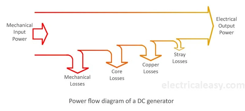
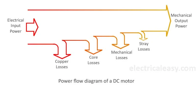
The most convenient method to understand these losses in a dc generator or a dc motor is using the power flow diagram. The diagram visualizes the amount of power that has been lost in various types of losses and the amount of power which has been actually converted into the output. Following are the typical power flow diagrams for a dc generator and a dc motor.

power flow diagram of a dc generator


power flow diagram of a dc motor

Read More...